Peripherals and I/O
Buses, devices, expanders, analog and digital pins - and the poll loop that reads them.
Beyond the panel and the touch controller, a board has sensors, expanders, analog inputs and
plain digital pins. The Buses, Devices and I/O tabs describe them, and the generator writes
hardware.h and hardware.cpp to bring them up and read them on a
schedule. Nothing here ever draws: the readings go into caches that
variables read.
Buses
The Buses tab declares I2C and SPI buses beyond the display's. An I2C bus has SDA,
SCL, a clock in kHz and an internal pull-up option (weak - fit 4.7 kΩ externals for anything but
the shortest run). An SPI bus has SCK, MOSI, an optional MISO, a clock in MHz and the SPI
mode. The first bus of a kind becomes Wire or SPI in the generated code,
the next Wire1 or SPI1, and so on up to what the MCU has. A device
attached to a bus that shares pins with the display's bus is legitimate and not flagged.
Devices
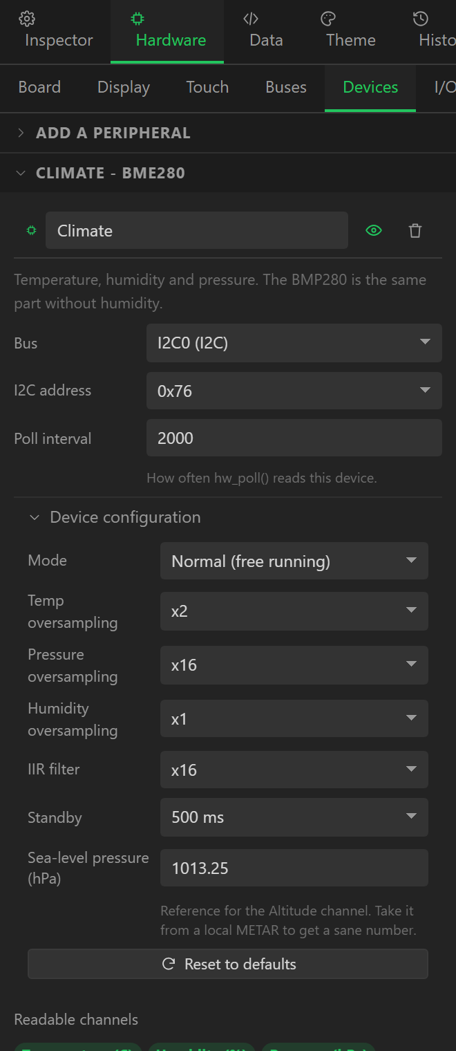
The Devices tab adds peripherals. Each has a Type, a Bus, an I2C
address or a CS pin depending on the bus, and a Poll interval - how often
hw_poll() reads it, independently of everything else, so a slow sensor never holds
up a fast one or the display. Below those comes the device's own configuration: every register
the driver library exposes, applied once in hw_init() after the device reports
present.
| Group | Device | Bus | Channels | Library | Configuration |
|---|---|---|---|---|---|
| Environment | BME280 | I2C | Temperature (C), Humidity (%), Pressure (hPa), Altitude (m) | adafruit/Adafruit BME280 Library | mode, osTemp, osPress, osHum, filter, standby, seaLevel |
| Environment | BMP280 | I2C | Temperature (C), Pressure (hPa) | adafruit/Adafruit BMP280 Library | mode, osTemp, osPress, filter, standby |
| Environment | SHT31 / SHT35 | I2C | Temperature (C), Humidity (%) | adafruit/Adafruit SHT31 Library | heater |
| Environment | AHT10 / AHT20 | I2C | Temperature (C), Humidity (%) | adafruit/Adafruit AHTX0 | - |
| Environment | SCD40 / SCD41 (CO2) | I2C | CO2 (ppm), Temperature (C), Humidity (%) | sparkfun/SparkFun SCD4x Arduino Library | tempOffset, altitude, asc |
| Environment | BH1750 (light) | I2C | Illuminance (lx) | claws/BH1750 | mode, mtreg |
| Environment | MCP9808 (temperature) | I2C | Temperature (C) | adafruit/Adafruit MCP9808 Library | resolution, wake |
| ADC | ADS1115 (16-bit ADC) | I2C | Channel 0 (V), Channel 1 (V), Channel 2 (V), Channel 3 (V), Differential 0-1 (V) | adafruit/Adafruit ADS1X15 | gain, rate |
| ADC | INA219 (current) | I2C | Bus voltage (V), Current (mA), Power (mW), Shunt voltage (mV) | adafruit/Adafruit INA219 | calibration |
| ADC | MAX17048 (battery gauge) | I2C | Cell voltage (V), State of charge (%) | adafruit/Adafruit MAX1704X | alertMin, alertMax |
| ADC | MCP3008 (8ch 10-bit ADC) | SPI | Channel 0 (counts), Channel 1 (counts), Channel 2 (counts), Channel 3 (counts), Channel 4 (counts), Channel 5 (counts), Channel 6 (counts), Channel 7 (counts) | adafruit/Adafruit MCP3008 | vref |
| Motion | MPU6050 (IMU) | I2C | Accel X (m/s2), Accel Y (m/s2), Accel Z (m/s2), Gyro X (rad/s), Gyro Y (rad/s), Gyro Z (rad/s), Temperature (C) | adafruit/Adafruit MPU6050 | accelRange, gyroRange, bandwidth, cycleMode |
| Motion | ADXL345 (accelerometer) | I2C | Accel X (m/s2), Accel Y (m/s2), Accel Z (m/s2) | adafruit/Adafruit ADXL345 | range, dataRate |
| Motion | VL53L0X (distance) | I2C | Distance (mm) | adafruit/Adafruit_VL53L0X | sense |
| Temperature | MAX6675 (thermocouple) | SPI | Temperature (C) | adafruit/MAX6675 library | settleMs |
| Temperature | MAX31855 (thermocouple) | SPI | Temperature (C), Cold junction (C) | adafruit/Adafruit MAX31855 library | settleMs |
| Time | DS3231 (RTC) | I2C | Hour, Minute, Second, Day, Month, Year, Unix time (s), Die temperature (C) | adafruit/RTClib | sqw, enable32k, setOnBoot |
| Storage | SD card | SPI | Card size (MB), Used (MB) | SD (bundled with the core) | freqMhz |
| Output | PCA9685 (16ch PWM) | I2C | - | adafruit/Adafruit PWM Servo Driver Library | pwmFreq, oscFreq, totemPole |
| Output | NeoPixel string (WS2812 / SK6812) | GPIO | Pixel count | adafruit/Adafruit NeoPixel | pixels, order, speed, brightness |
A device that fails to answer at boot is marked absent, its variables keep their initial
values, and the sketch says so on the serial monitor rather than hanging. Each device's library
is listed in LIBRARIES.md with the Library Manager search string.
Configuration worth knowing about
- BME280 / BMP280 - mode, per-channel oversampling, IIR filter, standby, and the
sea-level reference the altitude channel is computed from. The oversampling group is emitted
as one
setSampling()call. - SCD4x - temperature offset, altitude and automatic self-calibration. Changing these requires the measurement to be stopped and restarted, which the generated code brackets.
- ADS1115 - programmable gain and data rate; the channel readings are in volts after the gain is applied.
- INA219 - the shunt calibration preset.
- MPU6050 - accelerometer and gyro ranges, filter bandwidth, cycle mode.
- DS3231 - square-wave output, the 32 kHz pin, and set on boot, which writes the compile time into the clock on first run. Its Unix time channel is what a chart's time axis reads.
- PCA9685 and NeoPixel are outputs: they have no readable channels, and are driven by the Write to peripheral action or a Widget → variable binding.
- SD card - besides its size channels, this is the device that makes SD card available as the asset filesystem.
I/O extenders
Port expanders that add digital pins over I2C or SPI. Add one on the I/O tab with its
bus and address (or CS pin), and digital I/O entries can then be placed on its pins instead of
the MCU's. Each pin's direction is set by the entry that uses it, and the generated
ext_<name>_write() and _read() helpers are guarded by the
expander's presence.
| Extender | Bus | Pins | Library |
|---|---|---|---|
| PCF8574 | I2C | 8 | xreef/PCF8574 library |
| PCF8575 | I2C | 16 | xreef/PCF8575 library |
| MCP23017 | I2C | 16 | adafruit/Adafruit MCP23017 Arduino Library |
| MCP23S17 (SPI) | SPI | 16 | adafruit/Adafruit MCP23017 Arduino Library |
| CH422G | I2C | 12 | built in (no library) |
| TCA9554 / PCA9554 | I2C | 8 | built in (no library) |
| PCA9555 | I2C | 16 | built in (no library) |
The validator errors on an extender pin outside the part's width, on two entries claiming the same pin, and on an entry pointing at an extender that has been deleted. The same rules cover a display reset, touch reset or backlight routed through an extender (see Boards and displays).
The CH422G, TCA9554 and PCA9555 need no library: each is a few I2C register writes, and the
generator writes a small driver class into hardware.cpp for them. The PCF and MCP parts
use their Arduino libraries, listed in LIBRARIES.md as usual.
Analog inputs
An Analog input is an MCU ADC pin read and scaled. Fields:
| Field | Meaning |
|---|---|
| Pin | An ADC-capable GPIO on the chosen MCU. |
| Attenuation | ESP32 only: 11 dB (0-3.3 V), 6 dB (0-2.2 V), 2.5 dB (0-1.5 V) or 0 dB (0-1.1 V). |
| Samples | How many conversions are averaged per read. |
| Poll (ms) | How often it is read. |
| Smoothing | An exponential filter: 0 is raw, 0.2 is a good default, closer to 1 reacts faster. |
| Scaling | A linear map from a raw range (e.g. 0-4095) to a value range (e.g. 0-100). |
| Formula | Optional; overrides the scaling. raw is the averaged ADC count. |
| Unit | A label carried through to bindings. |
The ADC pins per MCU come from the catalogue - the ESP32 has 16, the S3 20, the C3 6, the RP2040 4 - and a pin that is not one of them is an error. The STM32 and ESP32-P4 entries currently have no ADC pins listed, so analog inputs are not offered on them.
Digital I/O
A Digital input or output on an MCU pin or an extender pin:
| Field | Meaning |
|---|---|
| Source | MCU pin or I/O extender. |
| Pin / Extender pin | The GPIO, or the extender and its pin number. |
| Active low | Active when the pin reads LOW. Everything downstream uses "active", not the raw level. |
| Pull-up | Enable the internal pull-up on an input. |
| Debounce (ms) | How long a level must hold before it counts. |
| Initial state | For an output: start active or not. |
Inputs are debounced in hw_poll() and exposed to variables as a Boolean; the
Digital input changes and Digital input held
automation triggers watch them. Outputs are driven by the
Set digital output action. "Active" respects the active-low setting throughout, so a
relay module that switches on LOW is described once and reads correctly everywhere.
What the generated code does
hardware.cpp declares one driver object per device and the bus objects they sit
on. hw_init() begins each bus, probes each device, applies its configuration and
records whether it answered. hw_poll(), called from app_poll() every
loop, checks each device's own timer and reads it when due into a cache struct. Reads are cheap
to ask for and never block on a slow part - a BME280 polled every two seconds costs nothing to a
label refreshed ten times a second. The Refresh inputs now action forces every timer
due at once.