Boards and displays
Every field on the Board, Display, Touch and Inputs tabs, and the tables behind them.
The Hardware tab describes the board the firmware will run on. A preset fills most of it in; this page explains every field so you can fill in a board that is not listed, or fix a preset that does not match the revision in your hand.
Verify the pinout. Vendors change pinouts between revisions of the same board and sell
several variants under one name. Every preset carries a note saying what to check, and the
generated README.md repeats it. Two minutes with the board's schematic before the
first flash is the cheapest debugging you will do.
Board
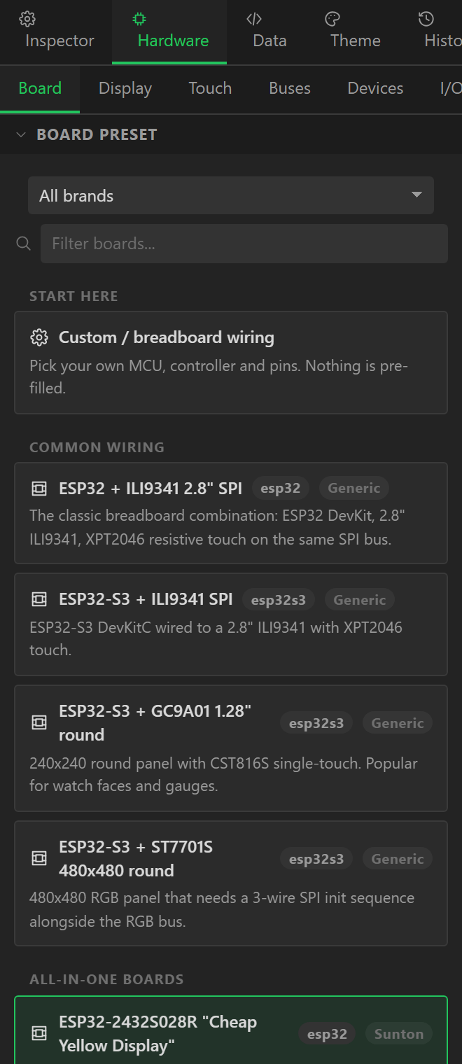
The Board tab has the preset list, filterable by brand, and below it the three things
a preset decides first: the MCU, whether PSRAM is enabled, and the FQBN -
the fully qualified board name the Arduino CLI and PlatformIO use, such as
esp32:esp32:esp32s3. Choosing a preset overwrites the Display, Touch and Inputs tabs
and the graphics library; it leaves your buses, devices, I/O, variables and automations alone.
Presets
| Preset | MCU | Panel | Resolution | Touch | Library | Verify |
|---|---|---|---|---|---|---|
| ESP32 + ILI9341 2.8" SPI | ESP32 (WROOM / WROVER) | ILI9341, SPI | 240 × 320 | XPT2046 | TFT_eSPI | Wiring template rather than a fixed board - adjust to match how you actually wired it. |
| ESP32-2432S028R "Cheap Yellow Display" | ESP32 (WROOM / WROVER) | ILI9341, SPI | 240 × 320 | XPT2046 | TFT_eSPI | Touch runs on its own VSPI bus, separate from the display HSPI bus. The 2432S028 also ships in a capacitive CST820 variant. |
| ESP32-2432S028C (capacitive CYD) | ESP32 (WROOM / WROVER) | ILI9341, SPI | 240 × 320 | CST820 | TFT_eSPI | The capacitive CYD shares GPIO21 between touch INT and the backlight on some revisions - check your board. |
| WT32-SC01 | ESP32 (WROOM / WROVER) | ST7796 / ST7796S, SPI | 320 × 480 | FT6236 / FT6336U | LovyanGFX | MISO is not broken out - leave it at -1. |
| M5Stack Core2 | ESP32 (WROOM / WROVER) | ILI9342 / ILI9342C, SPI | 320 × 240 | FT6236 / FT6336U | LovyanGFX | Backlight and panel reset are driven by the AXP192 over I2C, not by a GPIO. Initialise the PMIC before LVGL. |
| ESP32-S3 + ILI9341 SPI | ESP32-S3 | ILI9341, SPI | 240 × 320 | XPT2046 | LovyanGFX | Wiring template - change the pins to match your build. |
| ESP32-S3 + GC9A01 1.28" round | ESP32-S3 | GC9A01 / GC9A01A, SPI | 240 × 240 | CST816S | GFX Library for Arduino | The CST816S needs its RESET line wired or it will not answer on I2C. |
| Sunton ESP32-8048S043 (4.3" RGB) | ESP32-S3 | ST7262, RGB | 800 × 480 | GT911 | GFX Library for Arduino | PSRAM must be enabled (OPI, 80 MHz) or the RGB framebuffer will not allocate. |
| Sunton ESP32-8048S070 (7" RGB) | ESP32-S3 | ST7262, RGB | 800 × 480 | GT911 | GFX Library for Arduino | The RGB data pin order differs from the 4.3" board. Confirm against your board revision before flashing. |
| WT32-SC01 Plus | ESP32-S3 | ST7796 / ST7796S, PAR8 | 320 × 480 | FT6236 / FT6336U | LovyanGFX | CS is tied low on the board, so leave it at -1. |
| LilyGO T-Display-S3 | ESP32-S3 | ST7789, PAR8 | 170 × 320 | CST816S | GFX Library for Arduino | GPIO15 must be driven HIGH to enable the LCD power rail before init. The generated sketch does this for you. |
| LilyGO T-Display-S3 AMOLED | ESP32-S3 | RM67162, QSPI | 240 × 536 | CST226SE | GFX Library for Arduino | AMOLED brightness is set by a controller command, not a backlight GPIO. |
| Waveshare ESP32-S3-Touch-LCD-4.3 | ESP32-S3 | Generic RGB565 panel, RGB | 800 × 480 | GT911 | GFX Library for Arduino | Touch RESET and backlight hang off a CH422G I/O expander on I2C, not off GPIOs. |
| ESP32-S3 + ST7701S 480x480 round | ESP32-S3 | ST7701 / ST7701S, RGB | 480 × 480 | CST328 | GFX Library for Arduino | CS/SCK/MOSI carry the ST7701 init commands only; pixels go over the RGB bus. |
| STM32F407 + ILI9341 SPI | STM32F4 (F401 / F407 / F411) | ILI9341, SPI | 240 × 320 | XPT2046 | LovyanGFX | Needs the STM32duino core. SPI1 pins are remappable - check your variant. |
| STM32F407 + ILI9341 16-bit FSMC | STM32F4 (F401 / F407 / F411) | ILI9341, PAR16 | 240 × 320 | XPT2046 | LovyanGFX | These are the standard FSMC bank-1 pins. A16 (PD11) is wired to the RS/DC line. |
| STM32H7 + 800x480 RGB (LTDC) | STM32H7 | Generic RGB565 panel, RGB | 800 × 480 | FT5206 / FT5406 / FT5x06 | LovyanGFX | LTDC pin assignments are fixed per package. Generated code is a starting point - confirm against your datasheet. |
| Raspberry Pi Pico + ILI9341 | RP2040 (Pico / Pico W) | ILI9341, SPI | 240 × 320 | XPT2046 | TFT_eSPI | Only 264 KB of RAM - keep the LVGL draw buffer at roughly 1/10 screen. |
| Pico + GC9A01 round | RP2040 (Pico / Pico W) | GC9A01 / GC9A01A, SPI | 240 × 240 | none | TFT_eSPI | Pair it with a rotary encoder for input. |
Custom / breadboard wiring starts from an ESP32-S3 with LovyanGFX and nothing assigned, for hardware you wired yourself.
MCUs
The MCU decides which GPIOs exist, which are input-only, which carry warnings (flash, strapping, UART), which have ADC channels, whether PSRAM is possible, and which graphics libraries and buses are available.
| MCU | PSRAM | Input-only pins | Notes |
|---|---|---|---|
| ESP32 (WROOM / WROVER) | yes | 34, 35, 36, 37, 38, 39 | No native RGB parallel peripheral - use SPI or an 8/16-bit i80 bus. |
| ESP32-S3 | yes | - | The only common Arduino target with a hardware RGB565 LCD peripheral. PSRAM is effectively required for RGB panels. |
| ESP32-S2 | yes | 46 | Single core - keep lv_timer_handler() off the same loop as heavy work. |
| ESP32-C3 | no | - | No PSRAM. Keep the draw buffer small and prefer displays up to 320x240. |
| ESP32-C6 | no | - | No PSRAM. SPI displays only in practice. |
| ESP32-P4 | yes | - | Has a MIPI-DSI host and a 2D graphics accelerator (PPA). Arduino core support is newer - verify your core version. |
| STM32F4 (F401 / F407 / F411) | no | - | Use the STM32duino core. FSMC gives a fast parallel bus on F407 and up. |
| STM32F7 | no | - | Has an LTDC controller for true RGB panels plus DMA2D (Chrom-ART) acceleration. |
| STM32H7 | no | - | The strongest Arduino-compatible target for large panels. LTDC + DMA2D + external SDRAM. |
| RP2040 (Pico / Pico W) | no | - | PIO can drive an 8-bit parallel bus. Limited RAM - use a small partial draw buffer. |
| RP2350 (Pico 2) | yes | - | More RAM than RP2040 and optional PSRAM on boards such as the Pimoroni Pico Plus 2. |
Display
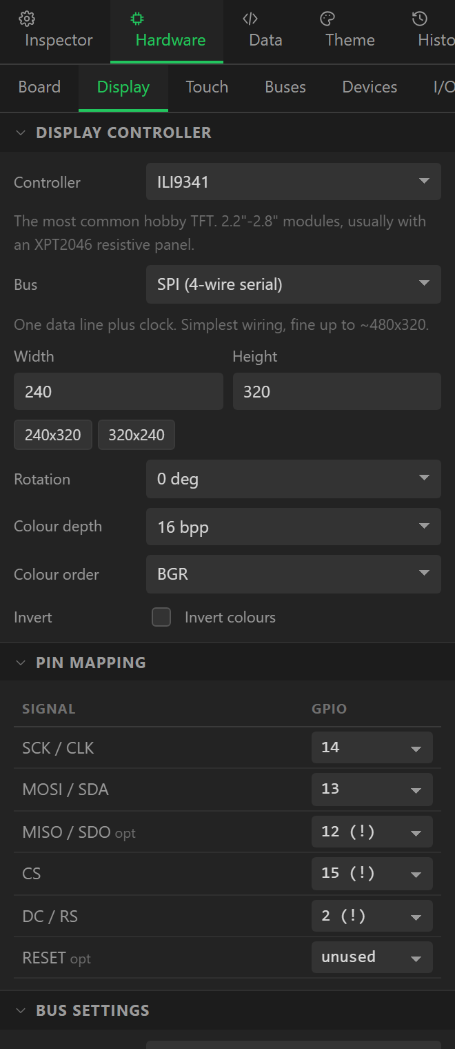
The Display tab: the panel Controller, the Bus, the pins for that bus, the Width and Height, Rotation (0, 90, 180 or 270), Colour depth, Colour order (RGB or BGR - the fix for red and blue being swapped), Invert (the fix for a negative image), and the bus options - the SPI clock in MHz, the SPI mode, and 3-wire for a 9-bit serial panel with no DC pin. The validator checks the resolution against what the controller documents and warns when it is not one of them.
Buses and their pins
| Bus | Pins |
|---|---|
| SPI | SCK, MOSI, MISO (optional), CS, DC, RST (optional) |
| QSPI | SCK, D0, D1, D2, D3, CS, RST (optional) |
| PAR8 | WR, RD (optional), DC, CS, RST (optional), D0, D1, D2, D3, D4, D5, D6, D7 |
| PAR16 | WR, RD (optional), DC, CS, RST (optional), D0, D1, D2, D3, D4, D5, D6, D7, D8, D9, D10, D11, D12, D13, D14, D15 |
| RGB | DE, VSYNC, HSYNC, PCLK, R0, R1, R2, R3, R4, G0, G1, G2, G3, G4, G5, B0, B1, B2, B3, B4, CS (optional), SCK (optional), MOSI (optional), RST (optional) |
| DSI | RST (optional), SDA (optional), SCL (optional) |
| I2C | SDA, SCL, RST (optional) |
Set a pin to -1 when the board does not wire it (a display MISO that is not broken
out, a CS tied low). The validator treats optional pins as optional and complains about required
ones.
Control lines on an I/O expander
On a growing number of boards the panel reset, the backlight enable and the touch reset are
not wired to GPIOs at all - they sit behind an I/O expander on I2C. The Waveshare
ESP32-S3-Touch-LCD-4.3 puts all three on a CH422G. For those, the RESET pin of the display
and of the touch controller, and the backlight pin, can be set to a pin on one of the
project's I/O extenders instead of a GPIO: the pin picker gains an On an I/O extender
group once an extender exists on the I/O tab. The generated sketch then brings the expander's bus
and the expander up first (hw_init_early()), pulses the resets through it, and drives
the backlight through it - on or off, since an expander pin cannot PWM. The pin header records
where each line went (#define LCD_RST -1 // RESET - on CH422G pin 3) and the README
wiring table says CH422G pin 3 rather than a GPIO.
Presets bring their own kit
Some presets add more than pins. Choosing the Waveshare 4.3" adds the I2C bus on GPIO 8/9 and the CH422G on it, with the three control lines already routed; the two Cheap Yellow Displays add their CN1 connector as an I2C bus on GPIO 27/22; the M5Stack Core2 adds Port A on 32/33. These items are tagged with the board they belong to: they survive re-applying the same preset, are dropped when you choose a different board, and never touch buses or devices you added yourself. Add a sensor to a board bus exactly as you would to one of your own.
Backlight
Pin, Active level, and PWM dimming, which on an ESP32 uses an LEDC channel at the PWM frequency you set, starting at the Default %. Without PWM the pin is simply driven to the active level. An AMOLED has no backlight pin; brightness is a controller command, which the driver handles.
Panel controllers
Thirty-six, across SPI, QSPI, 8- and 16-bit parallel, RGB565 and MIPI-DSI. Each entry knows which buses it supports, the resolutions it is sold in, and the driver symbol every graphics library expects for it.
| Controller | Buses | Documented resolutions |
|---|---|---|
| ILI9341 | SPI, PAR8, PAR16 | 240×320, 320×240 |
| ILI9341 (alt init) | SPI, PAR8 | 240×320 |
| ILI9342 / ILI9342C | SPI | 320×240 |
| ILI9481 | SPI, PAR8, PAR16 | 320×480 |
| ILI9486 | SPI, PAR8, PAR16 | 320×480 |
| ILI9488 | SPI, PAR8, PAR16 | 320×480 |
| ST7735 | SPI | 128×160, 128×128, 80×160 |
| ST7735S | SPI | 128×160, 80×160 |
| ST7789 | SPI, PAR8 | 240×320, 240×240, 135×240, 172×320 |
| ST7796 / ST7796S | SPI, PAR8, PAR16 | 320×480 |
| GC9A01 / GC9A01A | SPI | 240×240 |
| GC9107 | SPI | 128×128 |
| HX8357D | SPI, PAR8 | 320×480 |
| ILI9225 | SPI | 176×220 |
| R61581 | PAR8, PAR16 | 320×480 |
| NT35510 | PAR8, PAR16 | 480×800 |
| SSD1963 | PAR8, PAR16 | 480×272, 800×480, 800×600 |
| RA8875 | SPI, PAR8 | 480×272, 800×480 |
| SSD1351 | SPI | 128×128, 128×96 |
| SSD1331 | SPI | 96×64 |
| SSD1306 | I2C, SPI | 128×64, 128×32 |
| SH1106 | I2C, SPI | 128×64 |
| ST77916 | QSPI | 360×360, 400×400 |
| SH8601 | QSPI | 368×448, 390×390 |
| CO5300 | QSPI | 466×466, 410×502 |
| RM67162 | QSPI, SPI | 240×536 |
| NV3041A | QSPI | 480×272 |
| AXS15231B | QSPI | 320×480, 180×640 |
| Generic RGB565 panel | RGB | 800×480, 480×272, 1024×600, 480×480 |
| ST7262 | RGB | 800×480 |
| EK9716BD3 / EK73002 | RGB | 800×480 |
| ST7701 / ST7701S | RGB | 480×480, 480×800, 368×448 |
| GC9503V | RGB | 480×480 |
| EK79007 | DSI | 1024×600 |
| ILI9881C | DSI | 800×1280 |
| JD9365 | DSI | 800×1280 |
Graphics library
The library that drives the panel and gives LVGL its flush callback. Which ones are offered depends on the MCU and the bus:
| Library | Buses | MCUs | Notes |
|---|---|---|---|
| LovyanGFX | SPI, PAR8, PAR16, RGB, I2C | esp32, esp32s3, esp32s2, esp32c3, esp32c6, rp2040, rp2350, stm32f4, stm32f7, stm32h7 | Widest panel and bus coverage, DMA on ESP32. Configured with a C++ config class. |
| TFT_eSPI | SPI, PAR8, PAR16 | esp32, esp32s3, esp32s2, esp32c3, rp2040, rp2350, stm32f4, stm32f7 | Fastest for SPI panels on ESP32. Configured via User_Setup.h build defines. |
| GFX Library for Arduino | SPI, QSPI, PAR8, PAR16, RGB, I2C | esp32, esp32s3, esp32s2, esp32c3, esp32c6, rp2040, rp2350 | Moshi Liu's library. Best QSPI/AMOLED and RGB coverage. Configured in code. |
| esp_lcd (ESP-IDF component) | SPI, QSPI, PAR8, PAR16, RGB, DSI, I2C | esp32, esp32s3, esp32s2, esp32c3, esp32c6, esp32p4 | The vendor driver bundled with the ESP32 Arduino core. Lowest overhead, ESP32 only. |
TFT_eSPI is configured by a generated User_Setup.h (and the same defines in
platformio.ini); LovyanGFX by a generated LGFX_Config.hpp device class;
GFX Library for Arduino and esp_lcd in the sketch itself.
Touch
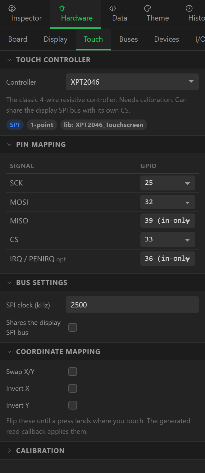
The Touch tab: the Controller, then the pins and options for its bus. An I2C controller takes SDA, SCL, an optional INT and an optional RESET, its I2C address, the I2C clock and whether it shares the display's I2C bus; an SPI controller takes SCK, MOSI, MISO, CS and an optional IRQ, the SPI clock and whether it shares the display's SPI bus (on by default, and right for most boards). Sharing is what lets the validator accept the same SCK on both without flagging a collision.
Below that, Swap X/Y, Invert X and Invert Y fix a touch that lands in the wrong place after rotation, and for a resistive controller a Calibration block holds the raw minimum and maximum in each axis.
Most capacitive controllers are read by generated register code over Wire and
need no library; the ones that do list it in LIBRARIES.md.
| Controller | Bus | Library |
|---|---|---|
| GT911 | I2C | TAMC_GT911 |
| GT9271 | I2C | bb_captouch |
| FT6206 | I2C | Adafruit_FT6206 |
| FT6236 / FT6336U | I2C | FT6236 |
| FT5206 / FT5406 / FT5x06 | I2C | bb_captouch |
| CST816S | I2C | CST816S |
| CST820 | I2C | bb_captouch |
| CST226SE | I2C | bb_captouch |
| CST328 | I2C | bb_captouch |
| TT21100 | I2C | esp_lcd_touch_tt21100 |
| CHSC6540 | I2C | bb_captouch |
| AXS15231B (touch half) | I2C | bb_captouch |
| FT3267 | I2C | bb_captouch |
| XPT2046 | SPI | XPT2046_Touchscreen |
| ADS7846 | SPI | XPT2046_Touchscreen |
| STMPE610 | SPI | Adafruit_STMPE610 |
| NS2009 | I2C | esp_lcd_touch_ns2009 |
| TSC2007 | I2C | Adafruit_TSC2007 |
Inputs
The Inputs tab adds LVGL input devices that are not touch:
- Rotary encoder - phase A and B pins and an optional push switch, with internal pull-ups, a reverse-direction option and the steps per detent. LVGL moves focus through a group of widgets, so an encoder needs widgets added to that group to reach them.
- Button pad - up to six buttons (up, down, left, right, enter, escape), each optional.
- Matrix keypad - row and column pins.
How pins are checked
Every assigned pin is checked against the MCU on every edit, and the result appears in the Check tab, the Errors tab and the export dialog:
- The pin must exist on the MCU.
- An input-only pin cannot drive CS, DC, RST or the backlight.
- Strapping and flash pins produce a warning naming the risk. They often are the right pin - the Cheap Yellow Display uses GPIO 2, 12 and 15 - so a warning is not an error.
- Two signals on one GPIO is an error, unless they are the shared lines of one named bus.
- The controller must support the bus, the MCU must have the bus, and the graphics library must have a driver for the controller on that bus.
- An RGB panel needs PSRAM; MIPI-DSI needs an ESP32-P4; an SPI clock above what the controller usually tolerates is warned about; a draw buffer too large for the MCU is warned about.
Rendering settings
In the export settings (Export > Export UI code > settings): Buffer height is the
partial draw buffer in lines - 40 by default, and the first thing to lower on a small MCU;
Double buffer allocates two so LVGL can render one while the other flushes;
Buffer in PSRAM puts them in external RAM on boards that have it. The sketch reports
draw buffer allocation failed - lower DRAW_BUF_LINES on the serial monitor if it
cannot get the memory.