Guition JC8012P4A1 10.1 inch ESP32-P4 (JC8012P4A1C_I_W_Y1)
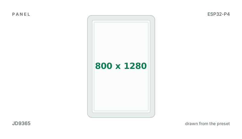
10.1" 800x1280 MIPI-DSI panel (JD9365) on an ESP32-P4, with an ES8311 speaker codec and a TF card. GSL3680 touch (one finger). Compiled, not yet seen on a board.
Building for it
A project is made for one toolchain, picked when you start it. For this board you can use one of the four:
| Toolchain | |
|---|---|
| Arduino (C++) | Every board, every widget and every peripheral here. The most control, and the most to set up. Start a project |
| MicroPython | The MicroPython export has not been built for this chip yet. It is written for the ESP32, S2, S3, C3 and C6. |
| ESPHome | The ESP32-P4 is only useful here with a MIPI-DSI panel, which this export does not write yet. |
| ESP-IDF (C) | The ESP-IDF export does not load the GSL3680's firmware or read it yet. The Arduino export does both. |
Wi-Fi: the ESP32-C6 beside the P4
The ESP32-P4 has no radio. This board’s Wi-Fi is an ESP32-C6 on the P4’s SDIO lines running Espressif’s ESP-Hosted, which has to be the release the ESP32 core was built with (2.12.11 for the core LCD Wizard exports for). A C6 as it leaves the factory may run an older one: the serial port then says ESP-Hosted of an unknown version, and Wi-Fi can fail or freeze the board as it starts. Update my C6 writes 2.12.11 to it from the browser, with no Wi-Fi and no password. Why, and how to update the C6.
- An older C6 may have to be flashed by hand. One whose ESP-Hosted is too old to take an update over the link refuses it, and nothing is written; it is then flashed through its own UART, as the board’s maker describes (how).
At a glance
| Part | Detail |
|---|---|
| Maker | Guition |
| MCU | ESP32-P4 RISC-V dual-core @ 400 MHz, 768 KB SRAM (+ PSRAM) |
| Display | Jadard JD9365, 800 x 1280 px, MIPI-DSI, 16-bit colour |
| Touch | Silead GSL3680 (capacitive, I2C) |
| Backlight | GPIO 23, dimmable (PWM) |
| Memory | 16 MB flash, 32 MB PSRAM (N16R32) |
| Graphics library | GFX Library for Arduino |
Display pins
JD9365 on MIPI-DSI: RGB colour order, inversion off.
| Signal | Pin |
|---|---|
| RESET | GPIO 27 |
| Backlight | GPIO 23 |
Touch pins
GSL3680: I2C address 0x40, 400 kHz, shares the display bus, X and Y swapped, X inverted.
| Signal | Pin |
|---|---|
| SDA | GPIO 7 |
| SCL | GPIO 8 |
| INT / IRQ | GPIO 21 |
| RESET | GPIO 22 |
Also on the board
- I2C (GPIO 7 / 8: touch, codec) - SDA GPIO 7, SCL GPIO 8
- SDCard - SD card, CLK GPIO 43, CMD GPIO 44, D0 GPIO 39, D1 GPIO 40, D2 GPIO 41, D3 GPIO 42
The TF card slot, on SDMMC 4-bit (CLK 43, CMD 44, D0-D3 39-42), as Guition's BSP has it. Guition power it from the chip's LDO channel 4. - WiFiCoprocessor - Wi-Fi co-processor, CLK GPIO 18, CMD GPIO 19, D0 GPIO 14, D1 GPIO 15, D2 GPIO 16, D3 GPIO 17, RST GPIO 54
The ESP32-C6 beside the P4 is this board's Wi-Fi, on SDIO CLK 18, CMD 19, D0-D3 14-17 and its CHIP_PU on GPIO 54 (reset low): Guition's schematic and the board's own stock firmware (ESP-Hosted host 2.11.0, slot 1, 4-bit, 40 MHz) agree, and they are the ESP32 core's own lines for the P4. It must run ESP-Hosted of the core's release (the README says how to tell).
The preset adds these to the Hardware tab with the board, so a sensor can go straight onto the connector.
Check your revision. Nobody at LCD Wizard has had this board: the export for it compiles and has not been seen on the panel. Every pin and setting is from Guition's own BSP for it: panel reset GPIO 27, backlight GPIO 23 (Guition drive it at 20 kHz), the JD9365 started with Guition's own table at 60 MHz, two lanes at 1500 Mbps, hsync 20/20/40 and vsync 4/8/20. If the panel stays dark with the backlight lit, choose "Type 1, 800x1280" as the start-up sequence on the Display tab, at 750 Mbps a lane: that is GFX Library for Arduino's own definition of the board, one row different. Touch is the board's GSL3680 (I2C 0x40 on GPIO 7/8, reset 22, interrupt 21), loaded with Guition's own firmware at every start; the serial log says whether it runs. Guition's driver also runs Silead's point-tracking code on every read, which the export leaves out: one finger is read, as the chip reports it, scaled from the chip's own 1648 x 880 (it reports landscape on this portrait glass), X and Y swapped and X inverted, as measured on a member's board. If touches land in the wrong place, the swap and invert settings on the Touch tab are where to correct it. The ES8311 speaker codec (MCLK 13, BCLK 12, LRCK 10, data 9, amplifier GPIO 20) is in the kit and off; its address 0x18 is the chip's default, not in Guition's code. A design on this preset builds for an ESP32-P4 before revision 3; if the upload reports revision 3 ("revision v3.1"), choose that under Hardware > Board > Chip revision. The ESP32-C6 is the board's Wi-Fi, on the pins its schematic and its stock firmware both give. Not driven: the microphone and the camera connector.
Designing for it in LCD Wizard
- Choose Guition JC8012P4A1 10.1 inch ESP32-P4 (JC8012P4A1C_I_W_Y1) on the Hardware tab (or use the button above) and every pin on this page is filled in. The export writes the sketch,
lcd_pins.h, the GFX Library for Arduino configuration,lv_conf.handplatformio.ini- a project that builds for this board as it comes. - The GSL3680 is capacitive and needs no calibration. The firmware resets it and checks it answers on every boot.
- The backlight is dimmable: give a slider or a button a Set backlight action.
- With PSRAM the LVGL memory pool can live there, leaving internal RAM for everything else.
- The MIPI-DSI panel stays on while settings or files are saved: the Arduino export keeps the frame running through flash writes, which otherwise blank an ESP32-P4 screen.
- Screens are designed for 800 x 1280 px in either orientation, with LVGL 9 or LVGL 8.
The parts
JD9365. ESP32-P4 only, with PSRAM. 800x1280, portrait; and 800x800 round, Waveshare's 3.4C. Compiled, not yet seen on a board.
GSL3680. Guition's JC8012P4A1 10.1" ESP32-P4 board. Needs both RST and INT: the chip is loaded with its firmware at every start.
ESP32-P4. Has a MIPI-DSI host and a 2D graphics accelerator (PPA). Arduino core support is newer - verify your core version.
GFX Library for Arduino. Moshi Liu's library. Best QSPI/AMOLED and RGB coverage. Configured in code.
The pinout on one page
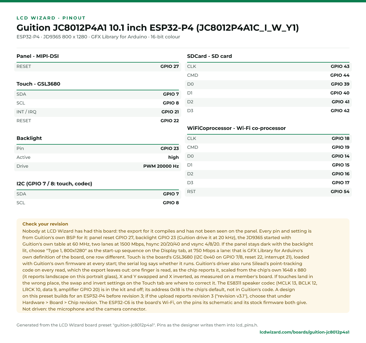
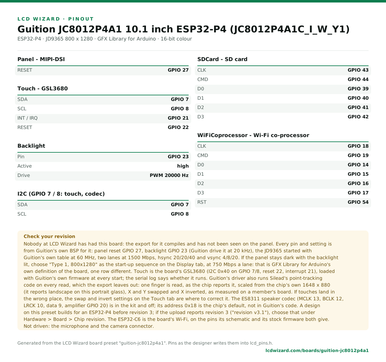
Every pin above, laid out to print and keep beside the bench. Generated from this preset, so it says exactly what the designer writes into lcd_pins.h.
Download the pinout (PNG)Open it as SVG
The same pins as data - board.json and pins.csv - are in the open pinout dataset on GitHub, free to reuse under CC BY 4.0.
Designs for this board
Nobody has published a design for this board yet. Publish yours from the designer and it appears here and in the gallery.
Similar boards
 Guition JC1060P470C 7 inch ESP32-P4 (JC1060P470C_I_W_Y)7" 1024x600 MIPI-DSI panel (JD9165) with GT911 touch on an ESP32-P4, wired 100 Mbit Ethernet, Wi-Fi through its ESP32-C6, an ES8311 speaker codec, a TF card and RS485. Compiled, not yet seen on a board.ESP32-P4 · JD9165 1024 x 600 · GT911 touch
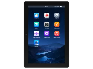 Waveshare ESP32-P4-WIFI6-Touch-LCD-10.110.1" 800x1280 MIPI-DSI panel (JD9365) with GT911 touch on an ESP32-P4, and Wi-Fi through its ESP32-C6. Compiled, not yet seen on a board.ESP32-P4 · JD9365 800 x 1280 · GT911 touchPurchase this board
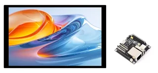 Waveshare ESP32-P4-NANO + 10.1-DSI-TOUCH-AWaveshare's 10.1" 800x1280 MIPI-DSI screen (JD9365) with GT911 touch on their ESP32-P4-NANO, whose backlight is a register on I2C. With the NANO's ES8311 codec, TF card, Ethernet and Wi-Fi through its ESP32-C6. Compiled, not yet seen on a bESP32-P4 · JD9365 800 x 1280 · GT911 touchPurchase this boardWaveshare ESP32-P4-NANO + 8-DSI-TOUCH-AWaveshare's 8" 800x1280 MIPI-DSI screen (JD9365) with GT911 touch on their ESP32-P4-NANO, whose backlight is a register on I2C. With the NANO's ES8311 codec, TF card, Ethernet and Wi-Fi through its ESP32-C6. Compiled, not yet seen on a boarESP32-P4 · JD9365 800 x 1280 · GT911 touchPurchase this board
 Waveshare ESP32-P4-WIFI6-Touch-LCD-3.4C3.4" 800x800 round IPS panel (JD9365) on MIPI-DSI with GT9271 touch on an ESP32-P4, an ES8311 speaker codec, a TF card, a camera connector and Wi-Fi through its ESP32-C6. Compiled, not yet seen on a board.ESP32-P4 · JD9365 800 x 800 · GT911 touch
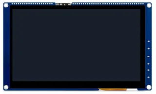 VIEWE ESP32-P4 SmartDisplay 7 inch (UEP4S070H1024V600C)7" 1024x600 MIPI-DSI panel (JD9165) with GT911 touch, an I2S speaker amplifier and Wi-Fi through an ESP32-C6 on an ESP32-P4. Seen running on a board before chip revision 3: the board test and the C6 update.ESP32-P4 · JD9165 1024 x 600 · GT911 touch
Next
- Quick start - from an empty screen to firmware on the board
- Boards and displays - presets, controllers, pins and touch in the designer
- Flashing and configuration - PlatformIO, the Arduino IDE and first-boot checks
- Troubleshooting - a white screen, mirrored image or touch that misses
- ESP32-P4 screen flickers when writing flash - NVS, LittleFS and OTA writes: the cause and the fix