Guition JC1060P470C 7 inch ESP32-P4 (JC1060P470C_I_W_Y)
7" 1024x600 MIPI-DSI panel (JD9165) with GT911 touch on an ESP32-P4, wired 100 Mbit Ethernet, Wi-Fi through its ESP32-C6, an ES8311 speaker codec, a TF card and RS485. Compiled, not yet seen on a board.
Building for it
A project is made for one toolchain, picked when you start it. For this board you can use two of the four:
| Toolchain | |
|---|---|
| Arduino (C++) | Every board, every widget and every peripheral here. The most control, and the most to set up. Start a project |
| MicroPython | The MicroPython export has not been built for this chip yet. It is written for the ESP32, S2, S3, C3 and C6. |
| ESPHome | The ESP32-P4 is only useful here with a MIPI-DSI panel, which this export does not write yet. |
| ESP-IDF (C) | Espressif's own framework: esp_lcd, the component registry and idf.py, with nothing of Arduino in it. Start a project |
At a glance
| Part | Detail |
|---|---|
| Maker | Guition |
| MCU | ESP32-P4 RISC-V dual-core @ 400 MHz, 768 KB SRAM (+ PSRAM) |
| Display | Jadard JD9165, 1024 x 600 px, MIPI-DSI, 16-bit colour |
| Touch | Goodix GT911 (capacitive, I2C) |
| Backlight | GPIO 23, dimmable (PWM) |
| Memory | 16 MB flash, 32 MB PSRAM (N16R32) |
| Graphics library | GFX Library for Arduino |
Display pins
JD9165 on MIPI-DSI: RGB colour order, inversion off.
| Signal | Pin |
|---|---|
| RESET | GPIO 0 |
| Backlight | GPIO 23 |
Touch pins
GT911: I2C address 0x5D, 400 kHz, shares the display bus.
| Signal | Pin |
|---|---|
| SDA | GPIO 7 |
| SCL | GPIO 8 |
| INT / IRQ | GPIO 21 |
| RESET | GPIO 22 |
Also on the board
- I2C (GPIO 7 / 8: touch, codec, I2C port) - SDA GPIO 7, SCL GPIO 8
- Ethernet - Ethernet PHY on RMII, MDC GPIO 31, MDIO GPIO 52, POWER GPIO 51
The RJ45 socket (100 Mbit/s): an IP101 PHY on the ESP32-P4's own Ethernet controller, on the chip's default RMII pins, its clock into GPIO 50, MDC 31, MDIO 52 and its reset on GPIO 51, as Guition's schematic has them. Wi-Fi, through the ESP32-C6, is the board's other network. - WiFiCoprocessor - Wi-Fi co-processor, CLK GPIO 18, CMD GPIO 19, D0 GPIO 14, D1 GPIO 15, D2 GPIO 16, D3 GPIO 17, RST GPIO 54
The ESP32-C6 inside the JC-ESP32P4-M3 module is this board's Wi-Fi, on the ESP32 core's own SDIO lines for the P4 (CLK 18, CMD 19, D0-D3 14-17, its CHIP_PU on GPIO 54). It must run ESP-Hosted of the core's release (the README says how to tell). The link runs at the core's 40 MHz, which an export cannot lower. - SDCard - SD card, CLK GPIO 43, CMD GPIO 44, D0 GPIO 39, D1 GPIO 40, D2 GPIO 41, D3 GPIO 42
The TF card slot, on SDMMC 4-bit. The core switches its supply with GPIO 45, which is also on the 2x13 header: leave that pin free. - RS485 - RS485 / Modbus RTU, TX GPIO 26, RX GPIO 27
The RS485 connector, on a MAX485 that turns itself round, so there is no direction pin: the board sends on GPIO 26 and receives on GPIO 27. The UART1 connector is the same two lines, so use one or the other.
The preset adds these to the Hardware tab with the board, so a sensor can go straight onto the connector.
Check your revision. Nobody at LCD Wizard has had this board: the export for it compiles and has not been seen on the panel or on a network. Pins are from Guition's own schematic for the JC1060P470C_I_W_Y (V1.0): panel reset GPIO 0, backlight GPIO 23 lit when high, the GT911 on GPIO 7/8 with INT 21 and RST 22, the ES8311 speaker codec (MCLK 13, BCLK 12, LRCK 10, data 9) with its amplifier on GPIO 11, the TF card on SDMMC (CLK 43, CMD 44, D0-D3 39-42), RS485 through a MAX485 that turns itself round (TX 26, RX 27, the same lines as the UART1 connector), and the RJ45 socket on an IP101 PHY wired to the ESP32-P4's own Ethernet pins (MDC 31, MDIO 52, reset 51, the clock in on 50). Guition changed the panel in 2026: a board whose label says V2 (SKU 10153004-V2) needs the V2 start-up sequence this preset starts with (52 MHz, 750 Mbps a lane, hsync 24/136/160, vsync 2/21/12, from the ESPHome community's configurations for it). If yours has no V2 on its label, choose "Guition JC1060P470 1024x600 (the library's table)" as the start-up sequence on the Display tab. The wrong one shows a white screen with a band of noise. Some older configurations give the panel reset as GPIO 5, which only reaches the header. GPIO 45, which the Arduino core switches as the TF card's power, is also on the 2x13 header. The touch controller may answer at 0x14 instead of 0x5D. A design on this preset builds for an ESP32-P4 before revision 3, which is what the community's configurations for this module build for; if the upload reports revision 3 ("revision v3.1"), choose that under Hardware > Board > Chip revision. Wi-Fi is the ESP32-C6 inside the module, in the kit as the Wi-Fi co-processor on the ESP32 core's own SDIO lines (CLK 18, CMD 19, D0-D3 14-17, its CHIP_PU on GPIO 54), beside the cable; it has to run ESP-Hosted of the core's release, which the board prints at start (see the README). The core runs that link at 40 MHz and an export cannot lower it; ESPHome configurations can, so if the picture streaks or the board restarts while Wi-Fi is busy, that is the difference to suspect. Wi-Fi through it compiles and has not been on a board. Not driven: the ES7210 microphones, the RX8025T clock chip, the battery charger (there is no battery reading), the MIPI-CSI camera connector and the C6's Bluetooth; ESP-NOW does not go through the C6.
Designing for it in LCD Wizard
- Choose Guition JC1060P470C 7 inch ESP32-P4 (JC1060P470C_I_W_Y) on the Hardware tab (or use the button above) and every pin on this page is filled in. The export writes the sketch,
lcd_pins.h, the GFX Library for Arduino configuration,lv_conf.handplatformio.ini- a project that builds for this board as it comes. - The GT911 is capacitive and needs no calibration. The firmware resets it and checks it answers on every boot.
- The backlight is dimmable: give a slider or a button a Set backlight action.
- With PSRAM the LVGL memory pool can live there, leaving internal RAM for everything else.
- Screens are designed for 1024 x 600 px in either orientation, with LVGL 9 or LVGL 8.
The parts
JD9165. ESP32-P4 only, with PSRAM. 1024x600 DSI panel: VIEWE's 7" ESP32-P4 SmartDisplay, Guition's JC1060P470 and JC1060P470C (the 2026 "V2" panel has a table of its own). Compiled, not yet seen on a board.
GT911. The address is selected by the INT pin level during reset, so wire INT and RST if you can.
ESP32-P4. Has a MIPI-DSI host and a 2D graphics accelerator (PPA). Arduino core support is newer - verify your core version.
GFX Library for Arduino. Moshi Liu's library. Best QSPI/AMOLED and RGB coverage. Configured in code.
The pinout on one page
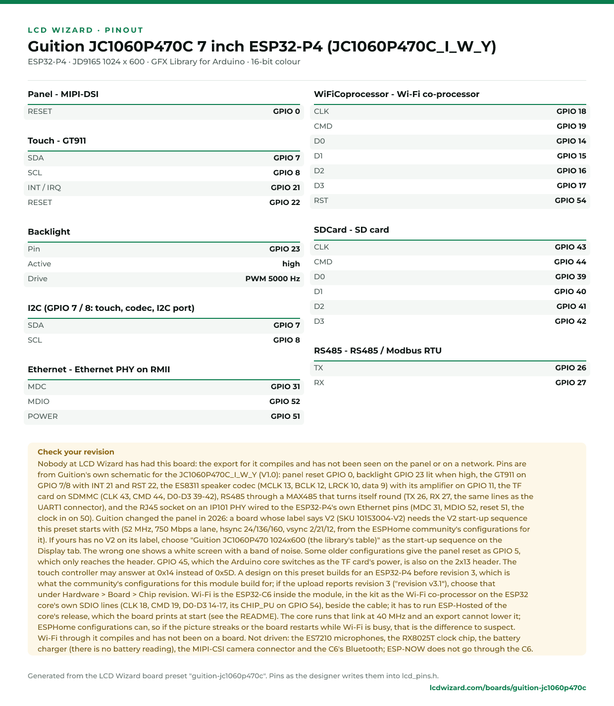
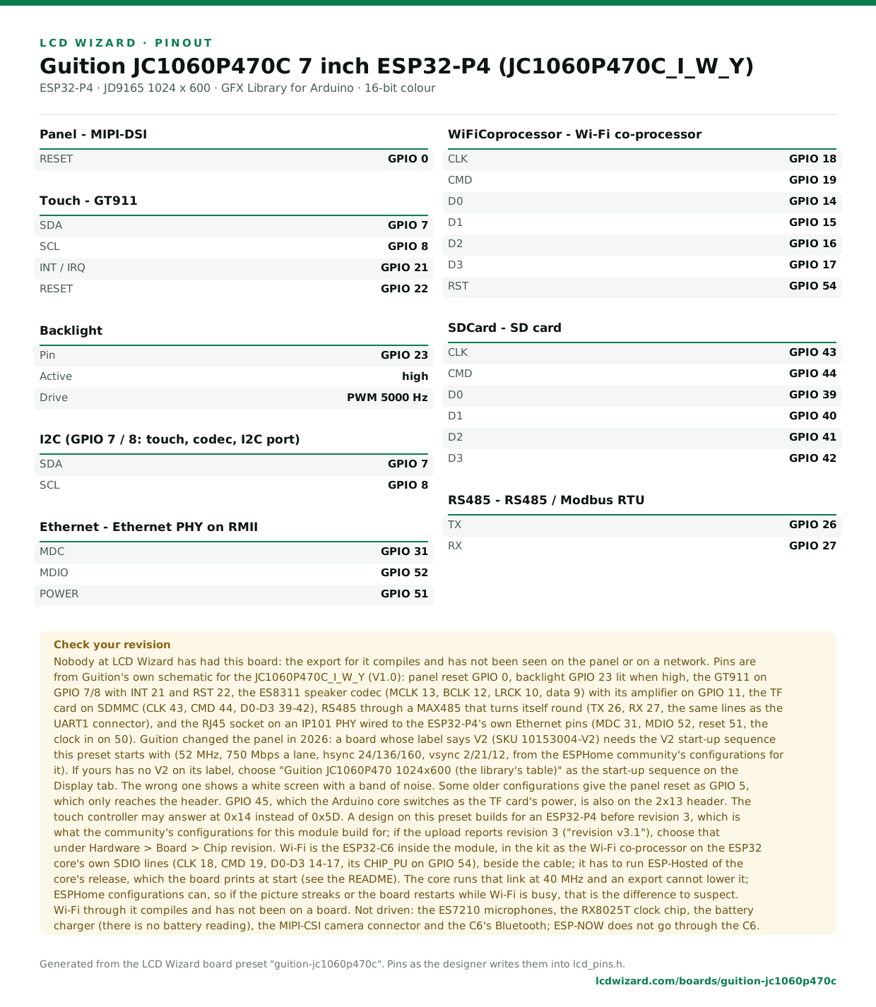
Every pin above, laid out to print and keep beside the bench. Generated from this preset, so it says exactly what the designer writes into lcd_pins.h.
Download the pinout (PNG)Open it as SVG
The same pins as data - board.json and pins.csv - are in the open pinout dataset on GitHub, free to reuse under CC BY 4.0.
From the people who made it
The board’s own documentation. Pinouts on vendor pages do sometimes disagree with the hardware in front of you - where this page and that one differ, trust your board and tell us.
- The vendor’s product page
- Vendor documentation
- Guition's schematic, JC1060P470C_I_W_Y-V1.0 (pins read from here), in a community mirror of Guition's files
- The 2026 V2 panel's start-up table and settings (espcontrol, ESPHome)
- Home Assistant forum thread on this board (V1 and V2 panels)
Designs for this board
Nobody has published a design for this board yet. Publish yours from the designer and it appears here and in the gallery.
Similar boards
 VIEWE ESP32-P4 SmartDisplay 7 inch (UEP4S070H1024V600C)7" 1024x600 MIPI-DSI panel (JD9165) with GT911 touch, an I2S speaker amplifier and Wi-Fi through an ESP32-C6 on an ESP32-P4. Compiled, not yet seen on a board.ESP32-P4 · JD9165 1024 x 600 · GT911 touch
 Elecrow CrowPanel Advanced ESP32-P4 7 / 9 / 10.1 inch1024x600 MIPI-DSI panel (EK79007) with GT911 touch, an I2S speaker amplifier and Wi-Fi through an ESP32-C6 on an ESP32-P4, the same board in 7, 9 and 10.1 inch sizes. Compiled, not yet seen on a board.ESP32-P4 · EK79007 1024 x 600 · GT911 touch
 Waveshare ESP32-P4-WIFI6-Touch-LCD-10.110.1" 800x1280 MIPI-DSI panel (JD9365) with GT911 touch on an ESP32-P4, and Wi-Fi through its ESP32-C6. Compiled, not yet seen on a board.ESP32-P4 · JD9365 800 x 1280 · GT911 touch
 Waveshare ESP32-P4-NANO + 10.1-DSI-TOUCH-AWaveshare's 10.1" 800x1280 MIPI-DSI screen (JD9365) with GT911 touch on their ESP32-P4-NANO, whose backlight is a register on I2C. With the NANO's ES8311 codec, TF card, Ethernet and Wi-Fi through its ESP32-C6. Compiled, not yet seen on a bESP32-P4 · JD9365 800 x 1280 · GT911 touchPurchase this board
 Waveshare ESP32-P4-NANO + 7-DSI-TOUCH-AWaveshare's 7" 720x1280 MIPI-DSI screen (ILI9881C) with GT911 touch on their ESP32-P4-NANO, whose backlight is a register on I2C. With the NANO's ES8311 codec, TF card, Ethernet and Wi-Fi through its ESP32-C6. Compiled, not yet seen on a boESP32-P4 · ILI9881C 720 x 1280 · GT911 touchPurchase this board
 Waveshare ESP32-P4-NANO + 8-DSI-TOUCH-AWaveshare's 8" 800x1280 MIPI-DSI screen (JD9365) with GT911 touch on their ESP32-P4-NANO, whose backlight is a register on I2C. With the NANO's ES8311 codec, TF card, Ethernet and Wi-Fi through its ESP32-C6. Compiled, not yet seen on a boarESP32-P4 · JD9365 800 x 1280 · GT911 touchPurchase this board
Next
- Quick start - from an empty screen to firmware on the board
- Boards and displays - presets, controllers, pins and touch in the designer
- Flashing and configuration - PlatformIO, the Arduino IDE and first-boot checks
- Troubleshooting - a white screen, mirrored image or touch that misses