ESP32-2432S028, two USB ports, ILI9341 (alt init)
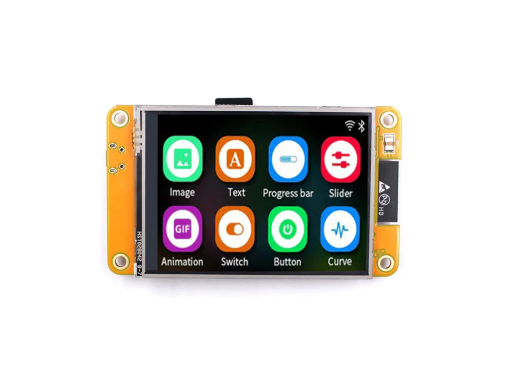
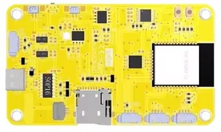
The CYD with two USB sockets (micro-USB and USB-C), marked ESP32-2432S028 without the R, whose ILI9341 needs the alternative start-up with colours inverted. Same pins as the original CYD. Not sure which CYD you have? The CYD diagnostic decides.
Got a CYD but not sure which one? Run the CYD diagnostic
About two minutes: it shows your board’s name and the settings to use.
When it’s done, pick the board it names in the designer. If it says no entry matches, paste the line from the serial monitor into a ticket.
Building for it
A project is made for one toolchain, picked when you start it. All four can drive this board:
| Toolchain | |
|---|---|
| Arduino (C++) | Every board, every widget and every peripheral here. The most control, and the most to set up. Start a project |
| MicroPython | Change a screen by editing a file on the board. No compiler once it is flashed. Start a project |
| ESPHome | No compiler to install, and the panel can join Home Assistant as real entities. Start a project |
| ESP-IDF (C) | Espressif's own framework: esp_lcd, the component registry and idf.py, with nothing of Arduino in it. Start a project |
At a glance
| Part | Detail |
|---|---|
| Maker | Sunton |
| MCU | ESP32 (WROOM / WROVER) Xtensa LX6 dual-core @ 240 MHz, 520 KB SRAM (+ up to 8 MB PSRAM on WROVER) |
| Display | Ilitek ILI9341 (alt init), 320 x 240 px, SPI (4-wire serial), 16-bit colour |
| Touch | XPTek XPT2046 (resistive, SPI) |
| Backlight | GPIO 21, dimmable (PWM) |
| Memory | 4 MB flash, no PSRAM (N4) |
| Graphics library | TFT_eSPI |
Display pins
ILI9341 (alt init) on SPI (4-wire serial): SPI clock 40 MHz, host HSPI, BGR colour order, inversion on.
| Signal | Pin |
|---|---|
| SCK / CLK | GPIO 14 |
| MOSI / SDA | GPIO 13 |
| MISO / SDO | GPIO 12 |
| CS | GPIO 15 |
| DC / RS | GPIO 2 |
| RESET | not connected |
| Backlight | GPIO 21 |
Touch pins
XPT2046: 2500 kHz, its own SPI bus, X and Y swapped.
| Signal | Pin |
|---|---|
| SCK | GPIO 25 |
| MOSI | GPIO 32 |
| MISO | GPIO 39 |
| CS | GPIO 33 |
| IRQ / PENIRQ | GPIO 36 |
Also on the board
- CN1 I2C (GPIO 27 / 22) - SDA GPIO 27, SCL GPIO 22
The preset adds these to the Hardware tab with the board, so a sensor can go straight onto the connector.
Check your revision. Two USB sockets and ESP32-2432S028 (no R) on the board; run the CYD diagnostic to be sure, since the same board ships with other screens. ILI9341 (alt init) with colours inverted is what a member's board of this kind needed on the ESP-IDF export (2026-11-11), and what LovyanGFX uses for this panel. On Arduino the alt init (TFT_eSPI's ILI9341_2_DRIVER) also sends its own gamma curve, which the ESP-IDF start-up does not, so shades may differ slightly between the two; not yet seen on this board. ESPHome has one ILI9341 start-up, so there the alt init is the same as the plain one. Touch: the first start calibrates it, whichever way the touch chip is wired.
Designing for it in LCD Wizard
- Choose ESP32-2432S028, two USB ports, ILI9341 (alt init) on the Hardware tab (or use the button above) and every pin on this page is filled in. The export writes the sketch,
lcd_pins.h, the TFT_eSPI configuration,lv_conf.handplatformio.ini- a project that builds for this board as it comes. - The XPT2046 is resistive, so the firmware calibrates it on the device: touch the crosses on the first boot after an upload and the result is saved. The screen says whether it worked.
- The backlight is dimmable: give a slider or a button a Set backlight action.
- Screens are designed for 320 x 240 px in either orientation, with LVGL 9 or LVGL 8.
The parts
ILI9341 (alt init). Alternate init sequence for clone panels that show inverted or shifted output.
XPT2046. The classic 4-wire resistive controller. Needs calibration. Can share the display SPI bus with its own CS.
ESP32 (WROOM / WROVER). No native RGB parallel peripheral - use SPI or an 8/16-bit i80 bus.
TFT_eSPI. Fastest for SPI panels on ESP32. Configured via User_Setup.h build defines.
The pinout on one page
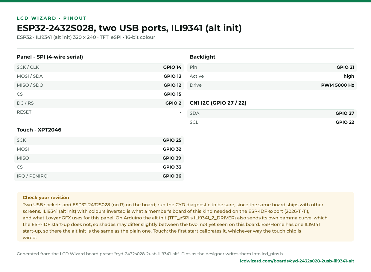
Every pin above, laid out to print and keep beside the bench. Generated from this preset, so it says exactly what the designer writes into lcd_pins.h.
Download the pinout (PNG)Open it as SVG
The same pins as data - board.json and pins.csv - are in the open pinout dataset on GitHub, free to reuse under CC BY 4.0.
Designs for this board
Nobody has published a design for this board yet. Publish yours from the designer and it appears here and in the gallery.
From the blog
Similar boards
 ESP32-2432S028 "Cheap Yellow Display", two USB ports, ILI9341The CYD with a micro-USB and a USB-C port, in its ILI9341 batch: 2.8" 240x320 ILI9341 with XPT2046 resistive touch on a second SPI bus. Same pins as the original CYD.ESP32 · ILI9341 240 x 320 · XPT2046 touchESP32-2432S028C (capacitive CYD)Capacitive variant of the Cheap Yellow Display: same ILI9341, CST820 touch over I2C.ESP32 · ILI9341 320 x 240 · CST820 touchESP32-2432S028R "Cheap Yellow Display", ST7789 versionThe CYD with an ST7789 screen (often the one with two USB ports, though some have one): 2.8" 240x320 ST7789 with XPT2046 resistive touch on a second SPI bus. Same pins as the original CYD.ESP32 · ST7789 240 x 320 · XPT2046 touchESP32-2432S028R "Cheap Yellow Display"2.8" 240x320 ILI9341 with XPT2046 resistive touch on a second SPI bus. The cheapest way into LVGL.ESP32 · ILI9341 320 x 240 · XPT2046 touchPurchase this board
 Guition JC2432W328R (2.8" resistive, one USB-C)Guition's 2.8" CYD in a clear case: 240x320 ST7789 with XPT2046 resistive touch on the panel's own SPI bus, backlight on GPIO 27, TF card, RGB LED, speaker and light sensor.ESP32 · ST7789 240 x 320 · XPT2046 touchGuition JC2432W328C (2.8" capacitive, one USB-C)Guition's 2.8" CYD in a clear case: 240x320 ST7789 with CST820 capacitive touch, backlight on GPIO 27, TF card, RGB LED, speaker and light sensor.ESP32 · ST7789 240 x 320 · CST820 touchPurchase this board
Next
- Quick start - from an empty screen to firmware on the board
- Boards and displays - presets, controllers, pins and touch in the designer
- Flashing and configuration - PlatformIO, the Arduino IDE and first-boot checks
- Troubleshooting - a white screen, mirrored image or touch that misses