Guition JC4827W543C (4.3" capacitive, ESP32-S3)
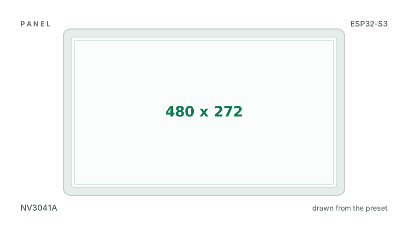
4.3" 480x272 IPS NV3041A over QSPI with GT911 capacitive touch, ESP32-S3 with 4 MB flash and 8 MB PSRAM, a TF card slot and a speaker output.
Building for it
A project is made for one toolchain, picked when you start it. For this board you can use one of the four:
| Toolchain | |
|---|---|
| Arduino (C++) | Every board, every widget and every peripheral here. The most control, and the most to set up. Start a project |
| MicroPython | The MicroPython export has no driver for this controller yet. |
| ESPHome | ESPHome has no driver for this controller. |
| ESP-IDF (C) | The NV3041A's quad SPI start-up is not among the quad panels the ESP-IDF export writes (the MicroPython export's, whose table it follows). The Arduino export drives it. |
At a glance
| Part | Detail |
|---|---|
| Maker | Guition |
| MCU | ESP32-S3 Xtensa LX7 dual-core @ 240 MHz, 512 KB SRAM (+ 2-16 MB PSRAM on most modules) |
| Display | NewVision NV3041A, 480 x 272 px, QSPI (quad SPI), 16-bit colour |
| Touch | Goodix GT911 (capacitive, I2C) |
| Backlight | GPIO 1, dimmable (PWM) |
| Memory | 4 MB flash, 8 MB octal PSRAM (N4R8) |
| Graphics library | GFX Library for Arduino |
Display pins
NV3041A on QSPI (quad SPI): QSPI clock 32 MHz, host SPI2_HOST, RGB colour order, inversion on.
| Signal | Pin |
|---|---|
| SCK | GPIO 47 |
| D0 - D3 | GPIO 21, 48, 40, 39 |
| CS | GPIO 45 |
| RESET | not connected |
| Backlight | GPIO 1 |
Touch pins
GT911: I2C address 0x5D, 400 kHz.
| Signal | Pin |
|---|---|
| SDA | GPIO 8 |
| SCL | GPIO 4 |
| RESET | GPIO 38 |
Also on the board
- SPI (TF card) - SCK GPIO 12, MOSI GPIO 13, MISO GPIO 11
- SDCard - SD card, on SPI (TF card), CS GPIO 10
The TF card slot, on SPI 12/13/11 with CS 10 (Guition's pin table).
The preset adds these to the Hardware tab with the board, so a sensor can go straight onto the connector.
Check your revision. From Guition's own package for the JC4827W543 (Arduino demos, pin table, getting-started guide): the NV3041A on QSPI (CS 45, CLK 47, D0-D3 21, 48, 40, 39, no reset line), started with Guition's own register table from the copy of GFX Library for Arduino they ship, IPS (inverted); backlight GPIO 1, lit high; GT911 touch at 0x5D on SDA 8, SCL 4, reset 38, polled (INT is GPIO 3, unused by Guition's code); TF card on SPI (CLK 12, MOSI 13, MISO 11, CS 10); speaker I2S (BCLK 42, LRCK 2, data 41). Guition's package has no schematic, and none of its code uses the TF card or the speaker: those are from the pin table alone. USB-C goes straight to the S3, so the serial log needs USB CDC On Boot (the export sets it); GPIO 17 and 18 are UART1 in the pin table. LCD_TE is on GPIO 0, the BOOT pin, so the BOOT button is not offered as an input. Guition's LVGL demos draw through a whole-frame canvas; the export draws in parts, as GFX Library for Arduino's own definition of this board does. Compiled, not yet seen on the glass: if colours are a negative, turn Invert off; if the picture is torn or misplaced, say so. The R (resistive) and N (no touch) models need other touch settings.
Designing for it in LCD Wizard
- Choose Guition JC4827W543C (4.3" capacitive, ESP32-S3) on the Hardware tab (or use the button above) and every pin on this page is filled in. The export writes the sketch,
lcd_pins.h, the GFX Library for Arduino configuration,lv_conf.handplatformio.ini- a project that builds for this board as it comes. - The GT911 is capacitive and needs no calibration. The firmware resets it and checks it answers on every boot.
- The backlight is dimmable: give a slider or a button a Set backlight action.
- With PSRAM the LVGL memory pool can live there, leaving internal RAM for everything else.
- Screens are designed for 480 x 272 px in either orientation, with LVGL 9 or LVGL 8.
The parts
NV3041A. 4.3" QSPI panel - RGB-like size without burning 16 pins.
GT911. The address is selected by the INT pin level during reset, so wire INT and RST if you can.
ESP32-S3. The only common Arduino target with a hardware RGB565 LCD peripheral. PSRAM is effectively required for RGB panels.
GFX Library for Arduino. Moshi Liu's library. Best QSPI/AMOLED and RGB coverage. Configured in code.
The pinout on one page
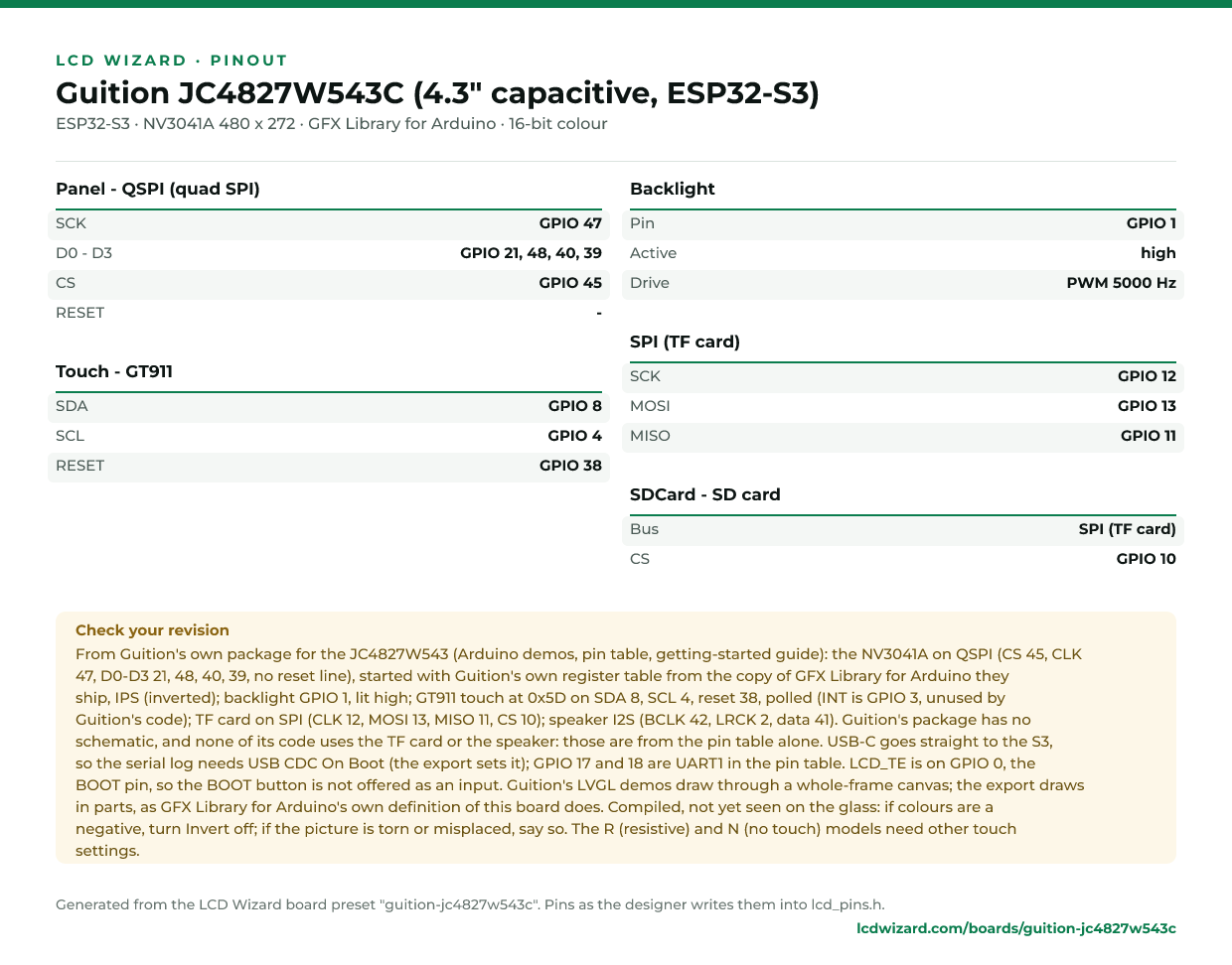
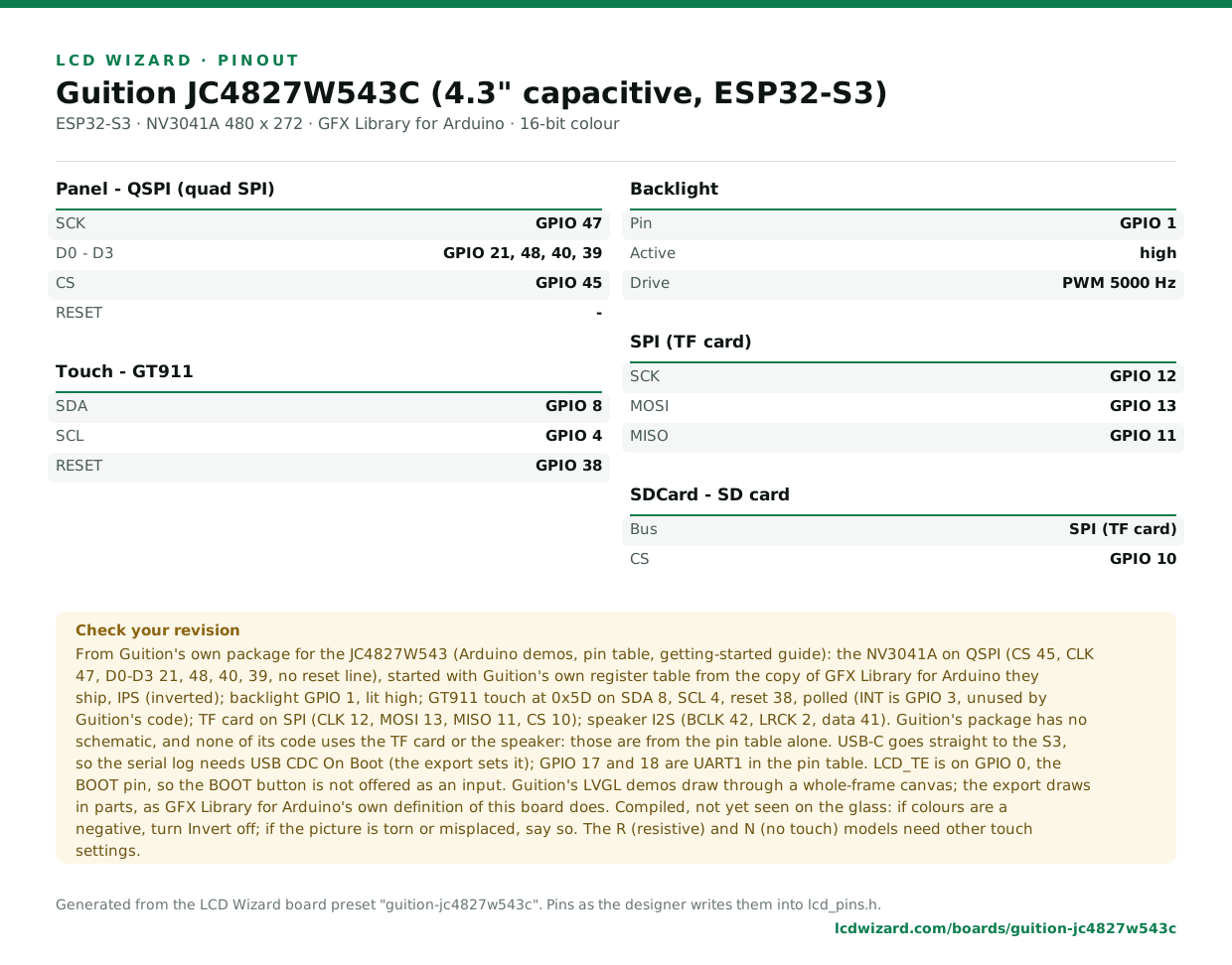
Every pin above, laid out to print and keep beside the bench. Generated from this preset, so it says exactly what the designer writes into lcd_pins.h.
Download the pinout (PNG)Open it as SVG
The same pins as data - board.json and pins.csv - are in the open pinout dataset on GitHub, free to reuse under CC BY 4.0.
Designs for this board
Nobody has published a design for this board yet. Publish yours from the designer and it appears here and in the gallery.
Similar boards
 Guition JC3248W535 (3.5" capacitive, ESP32-S3)3.5" 320x480 AXS15231B over QSPI with touch in the same chip, ESP32-S3 with 16 MB flash and 8 MB PSRAM, a TF card, an I2S speaker amplifier and battery charging.ESP32-S3 · AXS15231B 320 x 480 · AXS15231B (touch half) touch
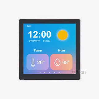 Guition ESP32-4848S040, relay version (4" 480x480)4" 480x480 square ST7701 panel with GT911 touch and three relays, sold as the "86 box" wall-plate unit.ESP32-S3 · ST7701 / ST7701S 480 x 480 · GT911 touch
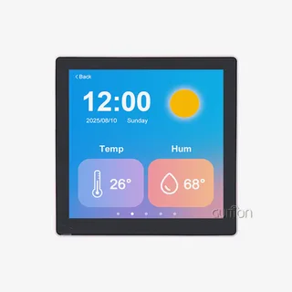 Guition ESP32-4848S040, speaker version (4" 480x480)4" 480x480 square ST7701 panel with GT911 touch and an NS4168 I2S speaker amplifier, the "86 box" wall-plate unit.ESP32-S3 · ST7701 / ST7701S 480 x 480 · GT911 touch
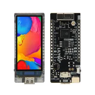 LilyGO T-Display-S3 AMOLED1.91" 240x536 RM67162 AMOLED over QSPI with CST226SE touch.ESP32-S3 · RM67162 240 x 536 · CST226SE touchPurchase this board
 Waveshare ESP32-S3-Touch-LCD-3.5B3.5" 320x480 AXS15231B over QSPI with touch in the same chip, an ES8311 codec with a microphone and speaker output, IMU, RTC, battery charging, a TF card and a camera connector.ESP32-S3 · AXS15231B 320 x 480 · AXS15231B (touch half) touchPurchase this board
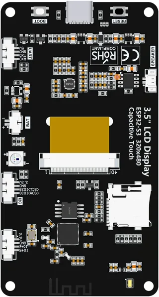 LCDWIKI 3.5" ESP32-S3 (ES3C35P)3.5" 320x480 ST77922 over QSPI with touch in the same chip, an ES8311 codec with microphone and speaker output, a WS2812 LED, a 4-bit SD slot and battery charging.ESP32-S3 · ST77922 320 x 480 · ST77922 (touch half) touchPurchase this board
Next
- Quick start - from an empty screen to firmware on the board
- Boards and displays - presets, controllers, pins and touch in the designer
- Flashing and configuration - PlatformIO, the Arduino IDE and first-boot checks
- Troubleshooting - a white screen, mirrored image or touch that misses