Waveshare ESP32-S3-Touch-LCD-4B
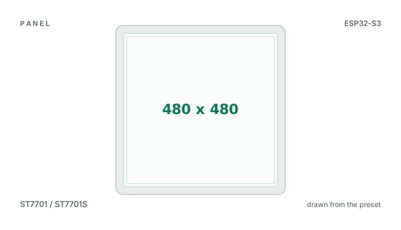
4" 480x480 square ST7701 panel (RGB) in an 86-box case, with GT911 touch, an ES8311 speaker codec and ES7210 microphones, a QMI8658 IMU, a PCF85063 RTC and an AXP2101 battery charger. A TCA9554 expander carries the panel's register load, it
Building for it
A project is made for one toolchain, picked when you start it. For this board you can use three of the four:
| Toolchain | |
|---|---|
| Arduino (C++) | Every board, every widget and every peripheral here. The most control, and the most to set up. Start a project |
| MicroPython | Change a screen by editing a file on the board. No compiler once it is flashed. Start a project |
| ESPHome | An ST7701 needs a register load written for its particular panel, sent over SPI alongside the RGB bus, and there is no generic one. ESPHome carries the sequence inside its model for a few named boards - the Guition ESP32-4848S040 among them - so pick one of those on the Board tab, or use the Arduino export, which can send every sequence the Display tab offers. |
| ESP-IDF (C) | Espressif's own framework: esp_lcd, the component registry and idf.py, with nothing of Arduino in it. Start a project |
At a glance
| Part | Detail |
|---|---|
| Maker | Waveshare |
| MCU | ESP32-S3 Xtensa LX7 dual-core @ 240 MHz, 512 KB SRAM (+ 2-16 MB PSRAM on most modules) |
| Display | Sitronix ST7701 / ST7701S, 480 x 480 px, RGB565 parallel (DPI), 16-bit colour |
| Touch | Goodix GT911 (capacitive, I2C) |
| Backlight | Always on, or controlled by the board |
| Memory | 16 MB flash, 8 MB octal PSRAM (N16R8) |
| Graphics library | GFX Library for Arduino |
Display pins
ST7701 / ST7701S on RGB565 parallel (DPI): RGB colour order, inversion off.
| Signal | Pin |
|---|---|
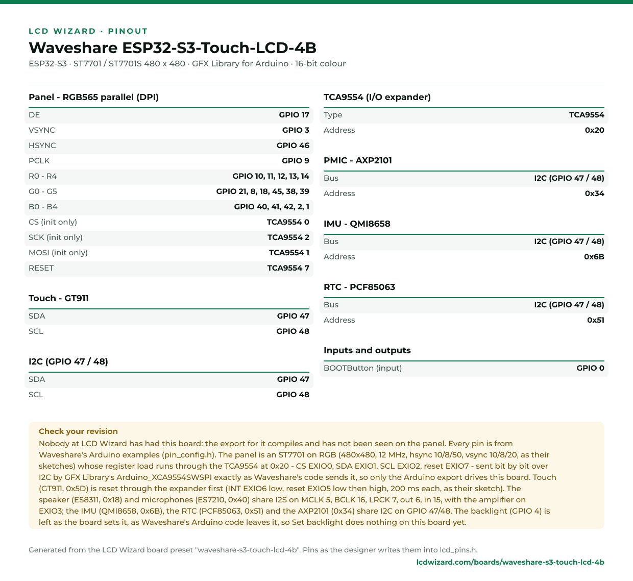
| DE | GPIO 17 |
| VSYNC | GPIO 3 |
| HSYNC | GPIO 46 |
| PCLK | GPIO 9 |
| R0 - R4 | GPIO 10, 11, 12, 13, 14 |
| G0 - G5 | GPIO 21, 8, 18, 45, 38, 39 |
| B0 - B4 | GPIO 40, 41, 42, 2, 1 |
| CS (init only) | TCA9554 pin 0 |
| SCK (init only) | TCA9554 pin 2 |
| MOSI (init only) | TCA9554 pin 1 |
| RESET | TCA9554 pin 7 |
Touch pins
GT911: I2C address 0x5D, 100 kHz, shares the display bus.
| Signal | Pin |
|---|---|
| SDA | GPIO 47 |
| SCL | GPIO 48 |
| RESET | not connected |
Also on the board
- I2C (GPIO 47 / 48) - SDA GPIO 47, SCL GPIO 48
- TCA9554 I/O expander at 0x20, driving the lines marked above
- PMIC - AXP2101, at 0x34, on I2C (GPIO 47 / 48)
- IMU - QMI8658, at 0x6B, on I2C (GPIO 47 / 48)
- RTC - PCF85063, at 0x51, on I2C (GPIO 47 / 48)
- TCA9554 pin 6 is set low at boot - Touch INT low
- TCA9554 pin 5 is set low at boot - Touch reset held
- TCA9554 pin 5 is set high at boot - Touch reset released
- BOOTButton - input on GPIO 0
The preset adds these to the Hardware tab with the board, so a sensor can go straight onto the connector.
Check your revision. Nobody at LCD Wizard has had this board: the export for it compiles and has not been seen on the panel. Every pin is from Waveshare's Arduino examples (pin_config.h). The panel is an ST7701 on RGB (480x480, 12 MHz, hsync 10/8/50, vsync 10/8/20, as their sketches) whose register load runs through the TCA9554 at 0x20 - CS EXIO0, SDA EXIO1, SCL EXIO2, reset EXIO7 - sent bit by bit over I2C by GFX Library's Arduino_XCA9554SWSPI exactly as Waveshare's code sends it, so only the Arduino export drives this board. Touch (GT911, 0x5D) is reset through the expander first (INT EXIO6 low, reset EXIO5 low then high, 200 ms each, as their sketch). The speaker (ES8311, 0x18) and microphones (ES7210, 0x40) share I2S on MCLK 5, BCLK 16, LRCK 7, out 6, in 15, with the amplifier on EXIO3; the IMU (QMI8658, 0x6B), the RTC (PCF85063, 0x51) and the AXP2101 (0x34) share I2C on GPIO 47/48. The backlight (GPIO 4) is left as the board sets it, as Waveshare's Arduino code leaves it, so Set backlight does nothing on this board yet.
Designing for it in LCD Wizard
- Choose Waveshare ESP32-S3-Touch-LCD-4B on the Hardware tab (or use the button above) and every pin on this page is filled in. The export writes the sketch,
lcd_pins.h, the GFX Library for Arduino configuration,lv_conf.handplatformio.ini- a project that builds for this board as it comes. - The GT911 is capacitive and needs no calibration. The firmware resets it and checks it answers on every boot.
- An RGB panel keeps its frame buffer in PSRAM, which this board has.
- Screens are designed for 480 x 480 px in either orientation, with LVGL 9 or LVGL 8.
The parts
ST7701 / ST7701S. RGB data plus a 3-wire SPI init sequence. You must wire CS/SCK/MOSI as well, and pick the init sequence your panel wants.
GT911. The address is selected by the INT pin level during reset, so wire INT and RST if you can.
ESP32-S3. The only common Arduino target with a hardware RGB565 LCD peripheral. PSRAM is effectively required for RGB panels.
GFX Library for Arduino. Moshi Liu's library. Best QSPI/AMOLED and RGB coverage. Configured in code.
The pinout on one page
Every pin above, laid out to print and keep beside the bench. Generated from this preset, so it says exactly what the designer writes into lcd_pins.h.
Download the pinout (PNG)Open it as SVG
The same pins as data - board.json and pins.csv - are in the open pinout dataset on GitHub, free to reuse under CC BY 4.0.
Designs for this board
Nobody has published a design for this board yet. Publish yours from the designer and it appears here and in the gallery.
Similar boards
 Waveshare ESP32-S3-Touch-LCD-2.8C2.8" 480x480 round IPS panel (ST7701, RGB) with GT911 touch, a TF card slot, QMI8658 IMU, PCF85063 RTC, a buzzer and battery sense. A TCA9554 expander handles the panel's reset and chip select and the touch reset.ESP32-S3 · ST7701 / ST7701S 480 x 480 · GT911 touch
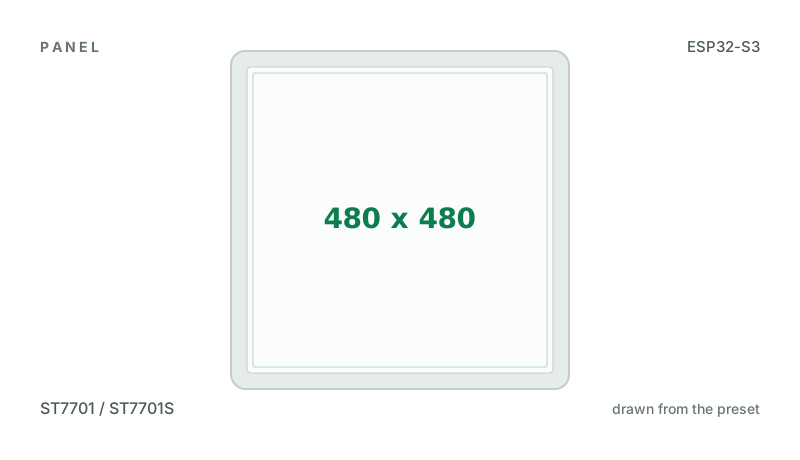
 Waveshare ESP32-S3-Touch-LCD-2.8B2.8" 480x640 IPS panel (ST7701, RGB) with GT911 touch, a TF card slot, QMI8658 IMU, PCF85063 RTC and battery sense. A TCA9554 expander handles the panel's reset and chip select and the touch reset.ESP32-S3 · ST7701 / ST7701S 480 x 640 · GT911 touchPurchase this board
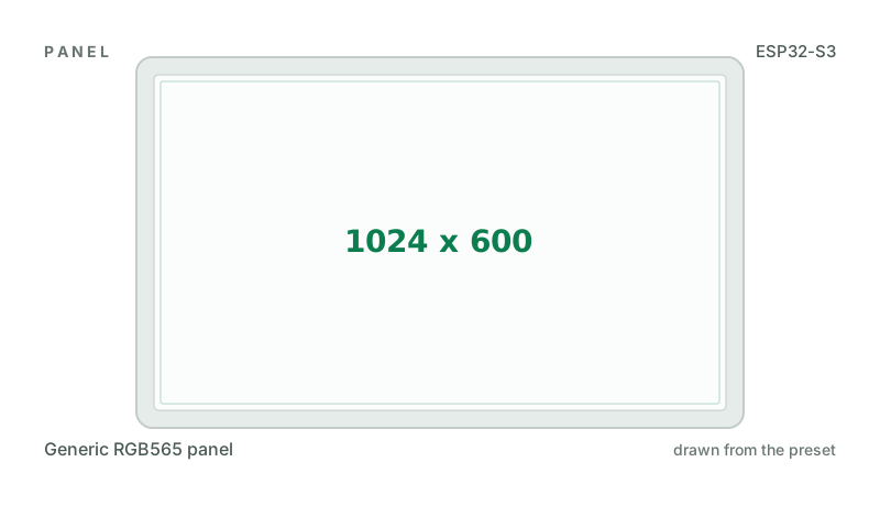
 Waveshare ESP32-S3-Touch-LCD-4 (V4.0)4" 480x480 square ST7701 panel (RGB) with GT911 touch, a TF card slot, RS485, CAN, a PCF85063 RTC, a buzzer and a battery charger. A CH32V003 helper chip handles the resets, backlight, buzzer and battery reading.ESP32-S3 · ST7701 / ST7701S 480 x 480 · GT911 touchPurchase this board
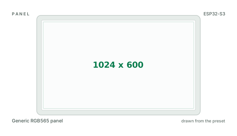
 Waveshare ESP32-S3-Touch-LCD-7B7" 1024x600 RGB IPS panel (ST7262) with GT911 touch, RS485, CAN, a TF card slot, a battery charger and a sensor terminal. Sold as the ESP32-S3-LCD-7B without the touch glass.ESP32-S3 · Generic RGB565 panel 1024 x 600 · GT911 touchPurchase this board
 Waveshare ESP32-S3-LCD-7B7" 1024x600 RGB IPS panel (ST7262) without touch, with RS485, CAN, a TF card slot, a battery charger and a sensor terminal. The ESP32-S3-Touch-LCD-7B without its touch glass.ESP32-S3 · Generic RGB565 panel 1024 x 600 · no touchPurchase this board
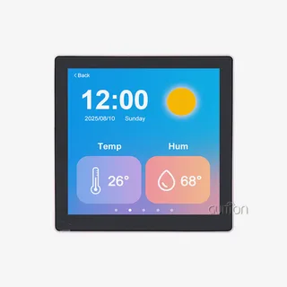 Guition ESP32-4848S040, speaker version (4" 480x480)4" 480x480 square ST7701 panel with GT911 touch and an NS4168 I2S speaker amplifier, the "86 box" wall-plate unit.ESP32-S3 · ST7701 / ST7701S 480 x 480 · GT911 touch
Next
- Quick start - from an empty screen to firmware on the board
- Boards and displays - presets, controllers, pins and touch in the designer
- Flashing and configuration - PlatformIO, the Arduino IDE and first-boot checks
- Troubleshooting - a white screen, mirrored image or touch that misses