RockBase IoT NM-CYD-C5 (ESP32-C5 "Cheap Yellow Display")
The Cheap Yellow Display with an ESP32-C5: 2.8" 240x320 ST7789 with XPT2046 resistive touch, SD card and touch all on the panel's SPI bus, an AHT20 temperature and humidity sensor, a WS2812 LED, a speaker amplifier and dual-band Wi-Fi 6. Sa
Building for it
A project is made for one toolchain, picked when you start it. For this board you can use three of the four:
| Toolchain | |
|---|---|
| Arduino (C++) | Every board, every widget and every peripheral here. The most control, and the most to set up. Start a project |
| MicroPython | The MicroPython export has not been built for this chip yet. It is written for the ESP32, S2, S3, C3 and C6. |
| ESPHome | No compiler to install, and the panel can join Home Assistant as real entities. Start a project |
| ESP-IDF (C) | Espressif's own framework: esp_lcd, the component registry and idf.py, with nothing of Arduino in it. Start a project |
At a glance
| Part | Detail |
|---|---|
| Maker | RockBase IoT |
| MCU | ESP32-C5 RISC-V @ 240 MHz, dual-band Wi-Fi 6, 384 KB SRAM, quad PSRAM on some modules |
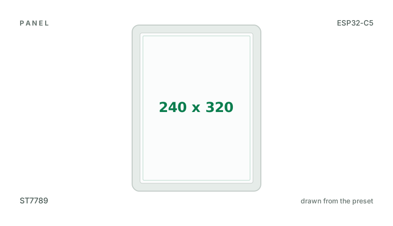
| Display | Sitronix ST7789, 240 x 320 px, SPI (4-wire serial), 16-bit colour |
| Touch | XPTek XPT2046 (resistive, SPI) |
| Backlight | GPIO 25, dimmable (PWM) |
| Memory | 16 MB flash, 8 MB quad PSRAM (N16R8) |
| Graphics library | GFX Library for Arduino |
Display pins
ST7789 on SPI (4-wire serial): SPI clock 20 MHz, host SPI2_HOST, BGR colour order, inversion off.
| Signal | Pin |
|---|---|
| SCK / CLK | GPIO 6 |
| MOSI / SDA | GPIO 7 |
| MISO / SDO | GPIO 2 |
| CS | GPIO 23 |
| DC / RS | GPIO 24 |
| RESET | not connected |
| Backlight | GPIO 25 |
Touch pins
XPT2046: 2500 kHz, shares the display bus.
| Signal | Pin |
|---|---|
| SCK | GPIO 6 |
| MOSI | GPIO 7 |
| MISO | GPIO 2 |
| CS | GPIO 1 |
Also on the board
- SPI (panel, touch and TF card) - SCK GPIO 6, MOSI GPIO 7, MISO GPIO 2
- I2C (GPIO 9 / 8, CN1) - SDA GPIO 9, SCL GPIO 8
- TempHumidity - AHT10 / AHT20, at 0x38, on I2C (GPIO 9 / 8, CN1)
- SDCard - SD card, on SPI (panel, touch and TF card), CS GPIO 10 (arrives switched off in a new design)
The TF card slot shares the panel's SPI lines (SCK 6, MOSI 7, MISO 2; CS 10 is its own), so it arrives switched off: switch it on with the eye beside its name under Hardware > Devices. - RgbLed - NeoPixel string, DATA GPIO 27
- Boot Button - input on GPIO 28
- Speaker - output on GPIO 26
The preset adds these to the Hardware tab with the board, so a sensor can go straight onto the connector.
Check your revision. Compiled, never run on a board. Pins are from RockBase IoT's wiki, their demo setups (gitee.com/Rockbase-iot/nm-cyd-c5) and the v1.0 schematic. Their Arduino demo uses a TFT_eSPI patched for the C5; this preset drives the same ST7789 with GFX Library for Arduino, the library's own start-up, at their 20 MHz. Colour order BGR and inversion off are their setting: if the picture is a negative turn Invert on, if red and blue are swapped set RGB. The display's reset is the board's EN line. Touch (XPT2046, CS 1) shares the panel's SPI bus and is read without its interrupt, as their code does (the schematic wires it to GPIO 3); it calibrates on first boot. The TF card (CS 10) shares that bus too and arrives switched off. The AHT20 and the CN1 header are on I2C, SDA 9 and SCL 8. The speaker amplifier is on GPIO 26: the C5 has no DAC, so it plays Beep tones, not audio files. Free for your own use: the GPS port P5 (GPIO 4 RX, 5 TX) and P1 (GPIO 4, 8, 26). The log is on the C5's own USB-C port (USB CDC On Boot); the other port is a CH340 on UART0.
Designing for it in LCD Wizard
- Choose RockBase IoT NM-CYD-C5 (ESP32-C5 "Cheap Yellow Display") on the Hardware tab (or use the button above) and every pin on this page is filled in. The export writes the sketch,
lcd_pins.h, the GFX Library for Arduino configuration,lv_conf.handplatformio.ini- a project that builds for this board as it comes. - The XPT2046 is resistive, so the firmware calibrates it on the device: touch the crosses on the first boot after an upload and the result is saved. The screen says whether it worked.
- The backlight is dimmable: give a slider or a button a Set backlight action.
- With PSRAM the LVGL memory pool can live there, leaving internal RAM for everything else.
- Screens are designed for 240 x 320 px in either orientation, with LVGL 9 or LVGL 8.
The parts
ST7789. Excellent colour and tolerates 80 MHz SPI. Many modules have no CS pin - tie it low and set CS to -1.
XPT2046. The classic 4-wire resistive controller. Needs calibration. Can share the display SPI bus with its own CS.
ESP32-C5. SPI displays. Quad PSRAM on the -R4/-R8 modules takes GPIO15.
GFX Library for Arduino. Moshi Liu's library. Best QSPI/AMOLED and RGB coverage. Configured in code.
The pinout on one page
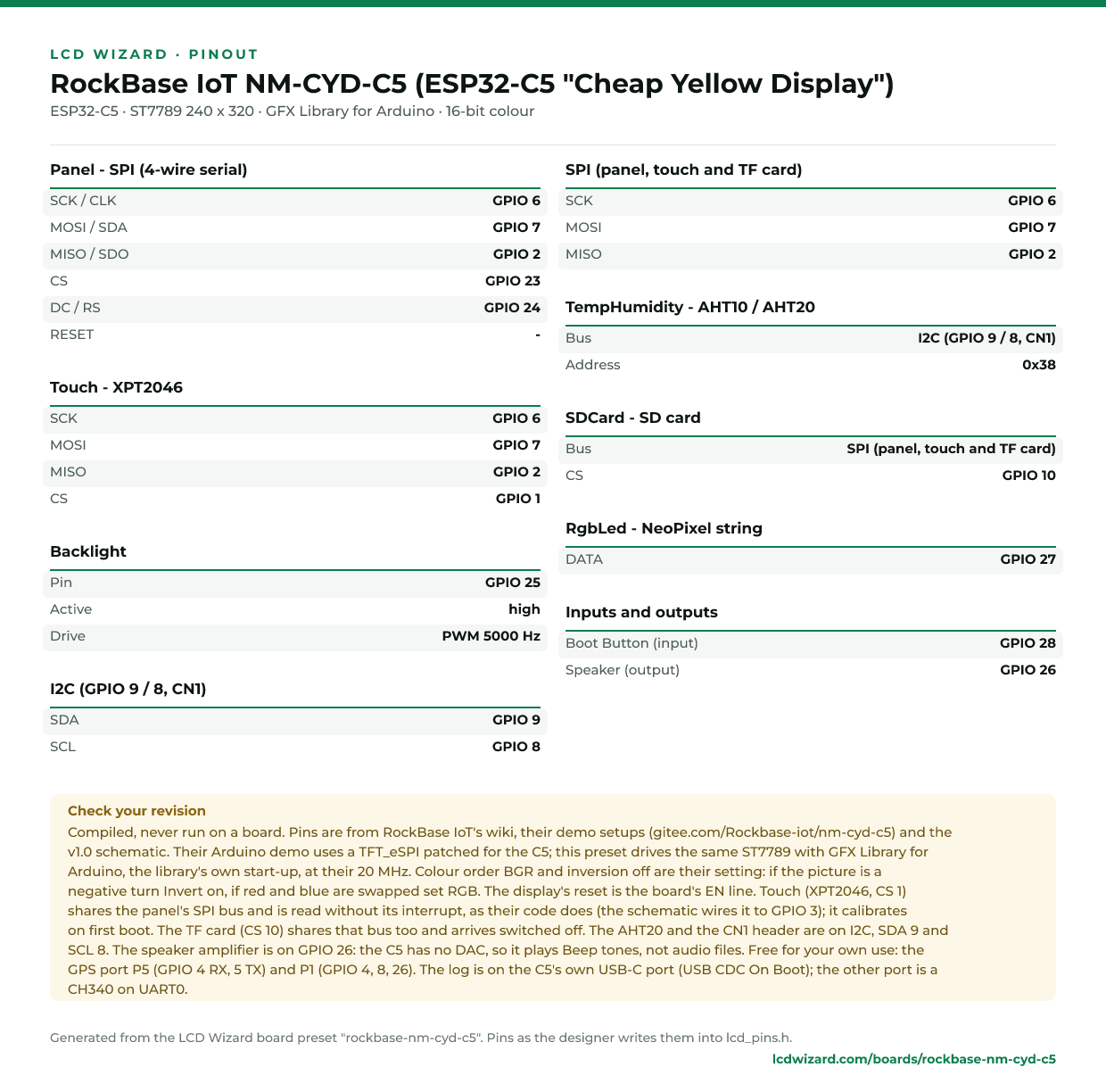
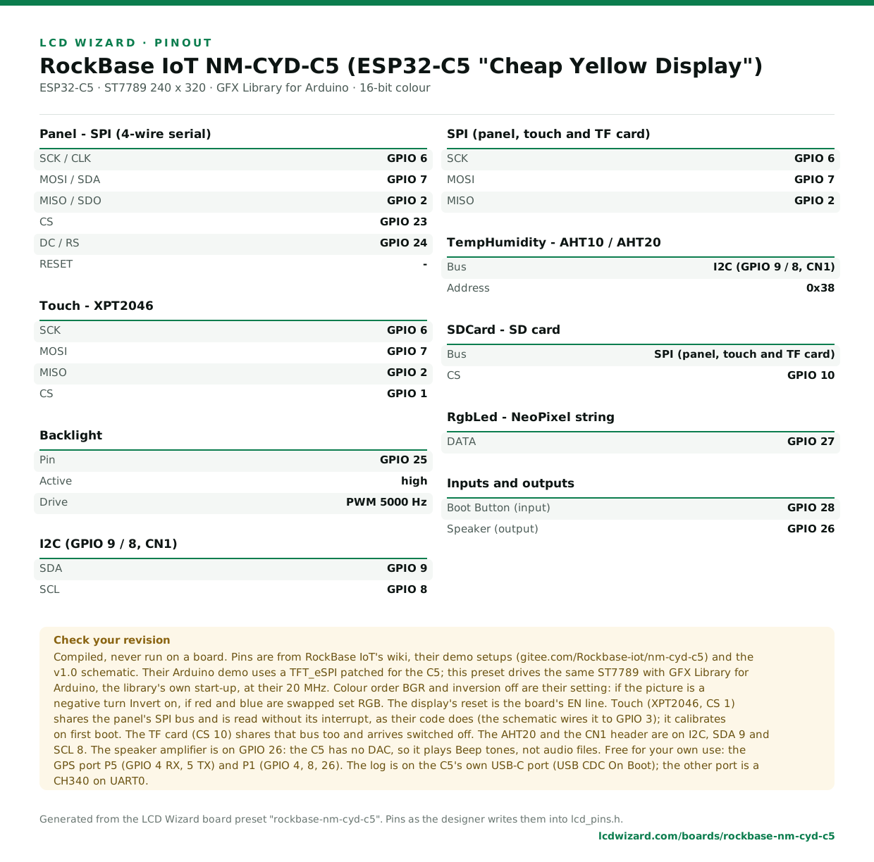
Every pin above, laid out to print and keep beside the bench. Generated from this preset, so it says exactly what the designer writes into lcd_pins.h.
Download the pinout (PNG)Open it as SVG
The same pins as data - board.json and pins.csv - are in the open pinout dataset on GitHub, free to reuse under CC BY 4.0.
Designs for this board
Nobody has published a design for this board yet. Publish yours from the designer and it appears here and in the gallery.
Similar boards
 Waveshare ESP32-C5-LCD-1.471.47" 172x320 TFT (ST7789, SPI), TF card.ESP32-C5 · ST7789 172 x 320 · no touchPurchase this board
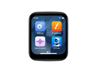 Waveshare ESP32-C5-Touch-LCD-1.691.69" 240x280 IPS LCD (ST7789V2, SPI), CST816T touch, ES8311 audio, QMI8658, PCF85063A.ESP32-C5 · ST7789 240 x 280 · CST816S touchPurchase this board
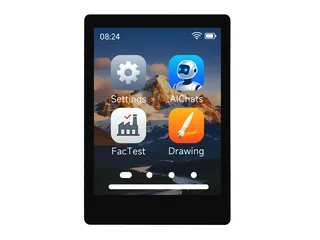 Waveshare ESP32-C5-Touch-LCD-2.82.8" 240x320 IPS LCD (ST7789 (docs link the ST7789V2 datasheet), SPI), CST3530 touch, ES8311 audio, TF card, QMI8658, PCF85063A.ESP32-C5 · ST7789 240 x 320 · CST3530 touchPurchase this board
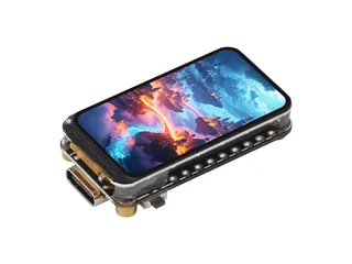 Waveshare ESP32-C3-LCD-1.471.47" 180x320 IPS LCD (ST7789T (driven by Waveshare's 'Vernon_ST7789T' esp_lcd component; docs spec table says 'ST7798', a typo), SPI), TF card, QMI8658.ESP32-C3 · ST7789 180 x 320 · no touchPurchase this board
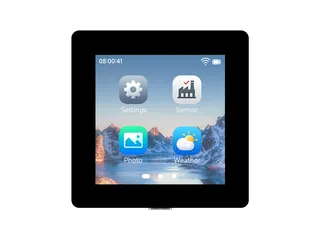 Waveshare ESP32-C5-LCD-2.732.73" 320x320 IPS LCD (ILI9488, SPI), TF card, QMI8658, PCF85063.ESP32-C5 · ILI9488 320 x 320 · no touchPurchase this board
 Waveshare ESP32-C5-Touch-LCD-3.53.5" 320x480 IPS LCD (ST7796, SPI), FT6336 touch, ES8311 speaker and microphone, TF card, AXP2101, QMI8658, PCF85063.ESP32-C5 · ST7796 / ST7796S 320 x 480 · FT6236 / FT6336U touch
Next
- Quick start - from an empty screen to firmware on the board
- Boards and displays - presets, controllers, pins and touch in the designer
- Flashing and configuration - PlatformIO, the Arduino IDE and first-boot checks
- Troubleshooting - a white screen, mirrored image or touch that misses